| CPC H05B 3/26 (2013.01) [H02S 40/12 (2014.12); H05B 2203/003 (2013.01); H05B 2203/014 (2013.01); Y02B 10/20 (2013.01); Y02B 10/70 (2013.01)] | 41 Claims |

|
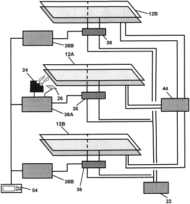
1. An autonomous solar panel system for use in winter conditions, the system comprising:
a master solar panel having a master energy transfer member associated therewith, the master energy transfer member comprising a combination of a master electrical vibration assembly and at least one of a master frame heater and a master electrical heater, the master electrical heater composed of a first serpentine wire disposed in proximity to a surface of the master solar panel, said master electrical vibration assembly comprising a master vibration actuator, a master vibration plunger and a master resilient vibration lever connected to the master solar panel, the master solar panel having an upper surface and at least one photovoltaic array for converting solar radiation to electrical energy;
a plurality of slave solar panels, each slave solar panel having a slave energy transfer member associated therewith, the slave energy transfer member comprising a combination of a slave electrical vibration assembly and at least one of a slave frame heater and a slave electrical heater, the slave electrical heater composed of a second serpentine wire disposed in proximity to the surface of the respective slave solar panel, the slave electrical vibration assembly comprising a slave vibration actuator, a slave vibration plunger and a slave resilient vibration lever connected to the respective slave solar panel, each slave solar panel having an upper surface and at least one photovoltaic array for converting solar radiation to electrical energy;
a winter precipitation sensor in communication with the master solar panel, the winter precipitation sensor having a top and a side and
i one or more radiation emitters for emitting radiation along a first axis towards an amount of winter precipitation on the master solar panel surface and
ii a radiation detector located adjacent the one or more radiation emitters, the radiation detector being located to receive reflected radiation from the winter precipitation along a second axis, the first axis being angled towards the second axis when viewed from the sensor top, both the first and second axes being at a same incidence angle to the master solar panel surface when viewed from the sensor side, the master solar panel surface reflecting emitter radiation angled away from the second axis on a basis of said incidence angle when viewed from the sensor side, the radiation detector producing a current flow signal proportional to the received irradiance, the one or more radiation emitters being located on either side of the radiation detector when viewed from the sensor top;
wherein the one or more radiation emitters includes two radiation emitters located on opposite sides of the radiation detector, the two radiation emitters being mounted to emit radiation along their respective first axe towards a common point on the master solar panel surface;
a master controller connected to the master solar panel;
a plurality of slave controllers, each slave controller being connected to a respective one of the plurality of slave solar panels;
an electrical power supply and charger connected to each of the master and slave energy transfer members; and
a network, to include the master and slave controllers, electrical heater switches, frame switches and electrical vibrator switches, interconnecting the energy transfer members, the sensor, and the electrical power supply, the network being configured such that in response to the winter precipitation sensor sensing an accumulation of winter precipitation on the master solar panel, the master controller directs a portion of stored power in the electrical power supply to activate first at least one of the master electrical heater and the master frame heater, followed by the master vibration activator, so as to autonomously remove the winter precipitation from the upper surface of the master solar panel and then the master controller directs the slave controllers sequentially to direct a portion of stored power in the electrical power supply to activate first at least one of the respective slave electrical heater and slave frame heater, followed by the respective slave vibration activator, so as to remove the winter precipitation from the upper surface of the respective slave solar panel.
|