| CPC H02M 7/5387 (2013.01) [H02M 1/14 (2013.01); H02P 27/08 (2013.01); H02P 29/68 (2016.02)] | 20 Claims |

|
1. An inverter device comprising:
an electrolytic capacitor which smooths an input voltage to generate a DC voltage;
an inverter circuit which generates an AC voltage from the DC voltage to drive an electric motor;
a temperature sensor which detects a temperature of the electrolytic capacitor or an ambient temperature of the electrolytic capacitor; and
a control device which controls the drive of a plurality of switching elements included in the inverter circuit,
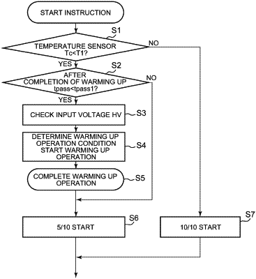
wherein in the case where the temperature detected by the temperature sensor is lower than a predetermined temperature, the control device on-drives specific switching elements selected out of the switching elements before starting a normal operation of the electric motor to thereby execute a warming up operation of allowing a current that controls a ripple voltage of the DC voltage in the electrolytic capacitor within a permissible range to flow through the electric motor at a predetermined rate of increase while keeping the electric motor stopped.
|