| CPC H02K 9/193 (2013.01) [H02K 5/203 (2021.01); H02K 11/215 (2016.01); H02K 11/33 (2016.01)] | 6 Claims |

|
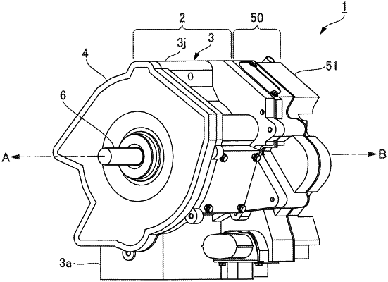
1. A rotary machine system comprising:
a rotary machine; an inverter configured to supply electric power to the rotary machine; and an oil pump configured to suck and discharge oil circulated in the rotary machine, wherein
the rotary machine and the inverter are adjacent to each other in a rotary machine axial direction,
at an adjacent portion, a shared wall forms a portion of a casing of the inverter on one side in the rotary machine axial direction and the shared wall forms a portion of a casing of the rotary machine on another side in the rotary machine axial direction, and
the oil pump includes a pump portion, a motor portion, and an electric portion arranged in a motor axis line direction, wherein the pump portion and the motor portion of the oil pump are disposed to penetrate through a through-hole of the shared wall and are disposed in the casing of the rotary machine, and the electric portion is disposed in the casing of the inverter.
|