| CPC H02K 1/278 (2013.01) [H02K 1/2786 (2013.01); H02K 5/04 (2013.01); H02K 7/003 (2013.01); H02K 7/08 (2013.01); H02K 15/14 (2013.01)] | 4 Claims |

|
1. A hollow shaft motor, comprising:
a housing 11 having a cylindrical shape; an upper cover 12 coupled to an upper portion of the housing 11;
a lower cover 15 coupled to a lower portion of the housing 11;
a stator assembly 20 located in the housing 11; and
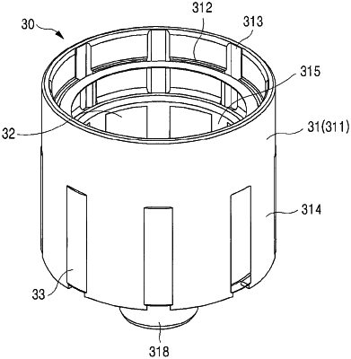
a rotor assembly 30 located in the stator assembly 20 to rotate, comprising a hollow shaft 31, a rotor core 32 coupled to the hollow shaft 31, and a plurality of magnets 33 arranged on an outer circumferential surface of the rotor core 32 at a certain interval, wherein the hollow shaft 31 is manufactured with a plastic resin by an insert injection molding in the state where the rotor core 32 and the magnet 33 are located in an insert injection mold,
wherein the hollow shaft 31 comprises a hollow shaft body 311 having a cylindrical shape; and a stepped part 312 protruding from an inside upper portion of the hollow shaft body 311 along an inner circumferential surface, wherein an upper bearing 13 is located and installed in the stepped part 312 in the inside upper portion of the hollow shaft body 311, and
wherein the hollow shaft 31 comprises an outer guide 314 extending downwardly along a lower outer circumferential surface of the hollow shaft body 311 at a certain interval in a longitudinal direction; and an inner guide 315 extending downwardly along a lower inner circumferential surface of the hollow shaft body 311 at a certain interval in a longitudinal direction, wherein the rotor core 32 and the magnet 33 are located between the outer guide 314 and the inner guide 315.
|