| CPC H01R 13/6592 (2013.01) [H01R 4/184 (2013.01); H01R 4/20 (2013.01); H01R 13/6473 (2013.01); H01R 13/6582 (2013.01)] | 6 Claims |

|
1. A connector structure, comprising:
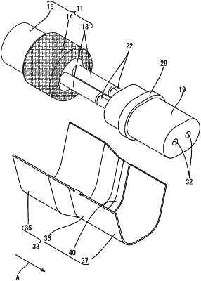
a shielded cable including:
a coated wire including a core and an insulation coating configured to surround an outer periphery of the core; and
a shield portion configured to surround an outer periphery of the coated wire;
an inner conductor including a core connecting portion connected to the core and a connecting portion continuous with the core connecting portion and connected to a mating terminal;
an insulating dielectric configured to surround at least an outer periphery of the connecting portion of the inner conductor; and
an outer conductor including a shield connecting portion electrically connected to the shield portion, the outer conductor surrounding at least the coated wire exposed from the shield portion,
wherein a part of the outer conductor corresponding to the coated wire exposed from the shield portion is formed with a projecting portion by causing a part of an inner surface of the outer conductor to project from other parts radially inwardly of the outer conductor such that the inner surface of the outer conductor becomes closer to the coated wire by a thickness of the projecting portion, the projecting portion being provided at a position corresponding to the coated wire exposed from the shield portion in a longitudinal direction of the outer conductor, and
an outer surface of the outer conductor is not depressed radially inwardly of the outer conductor.
|