| CPC H01R 13/187 (2013.01) [B60R 16/02 (2013.01); H01R 2201/26 (2013.01)] | 17 Claims |

|
1. An electrical connection device for a vehicle, the device comprising:
a male connector housing having a blade terminal mounting portion;
a female connector housing configured to couple to the male connector housing and having a tab terminal mounting portion;
a blade terminal mounted in the blade terminal mounting portion; and
a tab terminal mounted in the tab terminal mounting portion and configured to connect to the blade terminal when the male connector housing and the female connector housing are coupled to each other;
wherein the blade terminal comprises:
a terminal body having a first connection portion configured to accomplish electrical connection with the tab terminal; and
a contact spring assembled in a state of being inserted into an inner side of the first connection portion and configured to connect the terminal body and the tab terminal to each other by being brought into contact with the tab terminal when the tab terminal is inserted into the inner side of the first connection portion;
wherein the contact spring comprises:
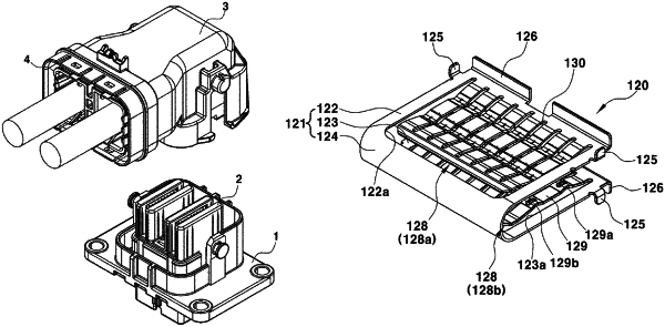
a fixed contact portion configured to be elastically brought into contact with an inner circumferential surface of the first connection portion in a state of being disposed at the inner side of the first connection portion, the fixed contact portion having a U-shaped cross section and configured to be inserted in a state of being compressed by being pressed when assembled by being inserted into the inner side of the first connection portion; and
a pair of movable contact portions integrally formed on upper and lower portions, respectively, of the fixed contact portion and configured to be elastically brought into contact with an outer circumferential surface of the tab terminal in a state of being pressed by the outer circumferential surface of the tab terminal inserted into the inner side of the first connection portion;
wherein each of the movable contact portions has a rear end and side ends separated from the fixed contact portion;
wherein each of the movable contact portions comprises a plurality of contact beams having front ends integrally formed with the fixed contact portion, respectively, and rear ends connected to each other;
wherein each of the contact beams has a front contact portion and a rear contact portion formed by bending a central portion thereof such that a height of the front contact portion is smaller than a height of the rear contact portion, the heights of the front contact portion and the rear contact portion being determined with the inner circumferential surface of the first connection portion as a reference;
wherein the front contact portion and the rear contact portion are protrudingly formed convexly toward an opposite side of the inner circumferential surface of the first connection portion at a center portion of the contact beam and each is configured to elastically press the outer circumferential surface of the tab terminal by elastic restoring force generated while being pressed by the outer circumferential surface of the tab terminal that is being inserted into the inner side of the first connection portion;
wherein the rear contact portion is disposed at a regular distance at a rear side of the front contact portion;
wherein the tab terminal is configured to be brought into contact with the front contact portion and then with the rear contact portion when being inserted into the inner side of the first connection portion; and
wherein the fixed contact portion comprises:
an upper plate configured to be elastically brought into contact with an upper inner circumferential surface of the first connection portion;
a lower plate configured to be elastically brought into contact with a lower inner circumferential surface of the first connection portion; and
a center plate bent in an arc shape at a rear end of the upper plate and a rear end of the lower plate and connecting the rear end of the upper plate and the rear end of the lower plate to each other.
|