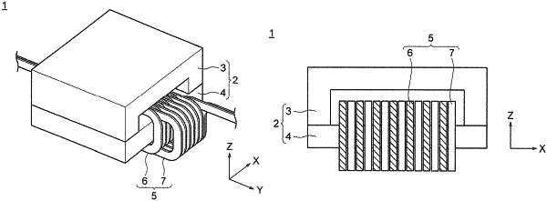
| CPC H01F 17/06 (2013.01) [H01F 27/006 (2013.01); H01F 27/22 (2013.01); H01F 2017/0093 (2013.01)] | 6 Claims |

|
1. A common mode choke coil, comprising:
a magnetic core; and
a pair of coils wound on a winding portion of the magnetic core,
wherein the pair of coils include a first pole coil and a second pole coil having a rectangular cylinder shape which are each wound on the winding portion in a spiral shape by N turns in a length direction of the winding portion,
wherein the first pole coil and the second pole coil are arranged on the winding portion so that a plurality of turns of the N turns are adjacent to each other,
wherein the adjacent first pole coil and second pole coil each include a parallel running portion and a non-parallel running portion, the first pole coil and the second pole coil overlapping each other in the parallel running portion, and separating from each other in a direction orthogonal to the length direction of the winding portion in the non-parallel running portion when the plurality of turns of the first pole coil and the second pole coil are viewed from the length direction of the winding portion,
where N is an integer of 2 or more, and
wherein the adjacent first pole coil and second pole coil each include the parallel running portions on two opposing sides of four sides that define the rectangular cylinder shape.
|