| CPC G07C 9/00563 (2013.01) [E05B 47/0001 (2013.01); E05B 67/00 (2013.01); F16P 3/00 (2013.01); F16P 3/08 (2013.01); G07C 9/00309 (2013.01); G07C 9/00571 (2013.01); G07C 9/00896 (2013.01); G07C 9/27 (2020.01); E05B 2047/0067 (2013.01)] | 9 Claims |

|
1. An equipment locking and de-energization management system comprising:
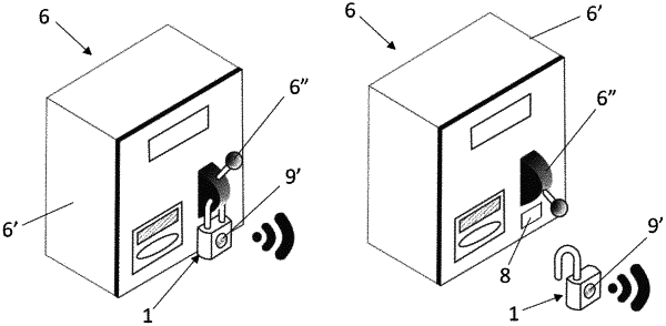
an intelligent lock (1) configured to be inserted into a power source (6) responsible for providing energy to the equipment (7),
the intelligent lock (1) comprising: a body (1′), a lock (1″), a communication interface (3) configured to communicate with and identify a communication element (8) of the power source (6), an electromechanical latch (4) capable of locking and unlocking the lock (1″) of the intelligent lock (1), an electronic processor (5) configured to process the information received and sent by means of the communication interface (3) and drive the electromechanical latch (4) of the intelligent lock (1), and a sensor (9) to identify whether the intelligent lock (1) is locked or unlocked; and
two mobile control devices (2), each mobile control device (2) comprising a communication interface (10) configured to communicate with the communication interface (3) of the intelligent lock (1), a visor (12) capable of displaying the information communicated between the intelligent lock (1) and at least one of the two mobile control devices (2), a reader element (11) configured to read an identifier (7′) fastened on the equipment (7), an identification element (13), and an electronic processor (14) configured to process the information received and sent from the reader element (11), the identification element (13) and the intelligent lock (1),
a central server (15) in communication with the communication interface (3) of the intelligent lock (1) and the communication interface (10) of each one of the mobile control devices (2), wherein the central server (15) is configured to intermediate the communication between the two mobile control devices (2), receive and relay data from the mobile control devices (2), and process, store and manage such data,
wherein the communication between the communication interface (3) of the intelligent lock (1) and the communication element (8) of the power source (6) identifies which intelligent lock (1) is fixed to which power source (6),
wherein the communication interface (3) of the intelligent lock (1) is configured to prevent the electromechanical latch (4) from locking the lock (1″) when the identification of the communication element (8) of the power source (6) does not correspond to the identification of the power source (6) of the equipment (7) intended for maintenance,
wherein the two mobile control devices (2) comprise: a first mobile control device (2) provided with the collaborators in charge of maintenance of the equipment (7) having the communication interface (10) in communication with the central server (15) and the reader element (11) in communication with the identifier (7′), and a second mobile control device (2) provided with the collaborators in charge of switching off and locking the power source (6) having the communication interface (10) in communication with the central server (15) and with the communication interface (3) of the intelligent lock (1),
wherein the identification element (13) of the first mobile control device (2) is configured to identify a person in charge of maintenance and the reader element (11) of the first mobile control device (2) is configured to read the identifier (7′) provided in the equipment (7) intended for maintenance,
wherein the identification element (13) of the second mobile control device (2) is configured to identify the person in charge of the de-energization and the power source (6) in which the intelligent lock (1) must be inserted.
|