| CPC G02B 23/2484 (2013.01) [G02B 23/243 (2013.01); H04N 23/55 (2023.01); A61B 1/00096 (2013.01); A61B 1/00183 (2013.01); A61B 1/051 (2013.01); H04N 23/555 (2023.01)] | 15 Claims |

|
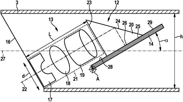
1. An observation instrument comprising a shaft and an imaging unit, the imaging unit comprising an objective lens system and an electronic image sensor arranged for picking up an image generated by the objective lens system, the imaging unit being pivotably arranged about a pivot axis in a distal end section of the shaft, the pivot axis of the imaging unit being transverse to a longitudinal axis of the distal end section of the shaft and essentially parallel to a pick-up surface of the image sensor; wherein the image sensor is arranged substantially parallel to an optical axis of the objective lens system; wherein the objective lens system comprises a plurality of optical elements, the optical elements of the objective lens system being fixedly positioned relative to each other within a sleeve; wherein the imaging unit comprises a deflection element comprising a deflection prism for deflecting light exiting from an image end of the objective lens system to an image pick-up surface of the image sensor, wherein the imaging unit is pivotable between a first end position, in which the optical axis of the objective lens system is approximately parallel to a longitudinal axis of the distal end section of the shaft, and a second end position, in which the optical axis of the objective lens system forms a maximal angle to the longitudinal axis of the distal end section of the shaft, and wherein the objective lens system and the electronic image sensor are pivotable as a unit with respect to the shaft, wherein a length, L, of the objective lens system is
L≤h/sin α−d/tan α
wherein h is an inner diameter of the distal end section of the shaft and d is a diameter of the objective lens system.
|