| CPC G01R 31/3171 (2013.01) [G01N 21/31 (2013.01); G02B 6/4226 (2013.01); G01N 2201/06113 (2013.01); G01N 2201/08 (2013.01)] | 16 Claims |

|
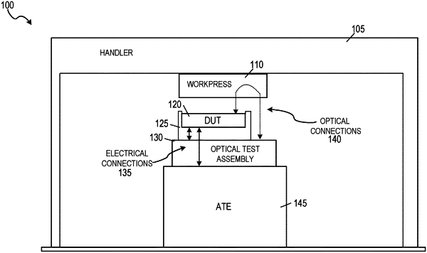
1. A method for testing an optical-electrical device under test (DUT) using an automated testing equipment (ATE) system, the method comprising:
aligning a load board optical interface between a load board of the ATE system and a mount assembly of the ATE system, a top-side of the load board supporting the optical-electrical DUT such that an electrical interface side of the optical-electrical DUT interfaces with electrical paths on the top-side of the load board to communicate one or more electrical signals from the optical-electrical DUT, the load board optical interface aligned by aligning a load board optical port of the load board with a first mount assembly optical port of the mount assembly;
aligning an optical device interface between the mount assembly and the optical-electrical DUT to communicate one or more optical signals generated by the optical-electrical DUT, the optical device interface aligned by aligning a second mount assembly optical port of the mount assembly with an optical port of the optical-electrical DUT that is on an optical interface side of the optical-electrical DUT that is opposite of the electrical interface side that faces the load board, wherein:
the first mount assembly optical port is optically coupled to the second mount assembly optical port by an optical coupling comprising one or more fiber optic cables such that light from the optical-electrical DUT propagates from the optical device interface through the optical coupling to the load board optical interface; and
analyzing the one or more electrical signals while analyzing the one or more optical signals from the optical-electrical DUT using the ATE system, the one or more electrical signals analyzed by an electrical test device of the ATE system that receives the one or more electrical signals from the electrical paths of the load board, the one or more optical signals analyzed by an optical testing device of the ATE system that receives the one or more optical signals via propagation through the optical device interface and the load board optical interface.
|