| CPC G01R 31/2621 (2013.01) | 18 Claims |

|
1. An apparatus for measuring dynamic on-resistance of a GaN-based device under test (DUT) comprising a first power terminal electrically connected to a first output node of a power supply, a second power terminal electrically connected to a second input node of the power supply, and a control terminal connected to an output of a first controlling module being configured to generate a first control signal to switch on and off the DUT, the apparatus comprising:
an input interface comprising a first input node configured for being electrically connected to the first power terminal of the DUT, a second input node configured for being electrically connected to the second power terminal of the DUT, and a control input node configured for being electrically connected to the output of the first controlling module;
an output interface comprising a first output node configured for being electrically connected to a first signal input node of an electrical signal monitoring equipment and a second output node connected to the second input node and configured for being electrically connected to a second signal input node of the electrical signal monitoring equipment;
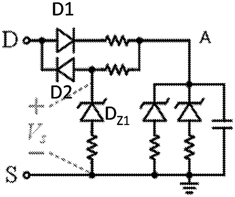
a switching device comprising a control terminal, a first power terminal electrically connected to the first input node, and a second power terminal electrically coupled to the first output node through an impedance matching module and coupled to the second output node through a noise absorption circuit module;
a second controlling module comprising an input terminal electrically connected to the control input node and an output terminal electrically connected to the control terminal of the switching device; and being configured to:
receive the first control signal from the first controlling module; and generate a second control signal to switch on and off the switching device such that the switching device is turned on later than the DUT for a first time interval and turned off earlier than the DUT for a second time interval,
wherein the second controlling module comprises:
a driving module configured to receive a driver input signal and an enabling signal, and generate the second control signal to switch on and off the switching element;
a first delay module configured to receive the first control signal and generate the driver input signal to the driving module;
a second delay module configured to receive the first control signal; and
a level reversal module connected to the second delay module and configured to generate the enabling signal to the driving module.
|