| CPC G01N 15/088 (2013.01) [E21B 49/02 (2013.01); E21B 49/0875 (2020.05); G01N 15/0826 (2013.01); G06T 17/00 (2013.01); G06T 17/05 (2013.01); G01N 2015/0846 (2013.01)] | 10 Claims |

|
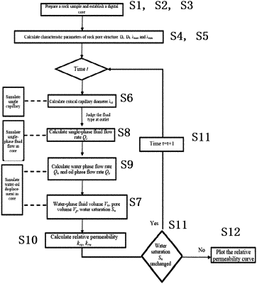
1. A digital imaging technology-based method for calculating relative permeability of tight core, comprising the following steps:
Step S1: preparing a small column sample of tight core satisfying resolution requirements;
Step S2: scanning the sample by MicroCT-400 and establishing a digital core;
Step S3: performing statistical analysis on parameters reflecting rock pore structures and shape characteristics according to the digital core;
Step S4: calculating a tortuosity fractal dimension DT and a porosity fractal dimension Df by a 3D image fractal box dimension algorithm;
Step S5: performing statistical analysis on maximum pore equivalent diameter λmax and minimum pore equivalent diameter λmin by a label;
Step S6: simulating a water-oil displacement in single fractal capillary, calculating a critical capillary diameter λcr, and obtaining the critical capillary diameter at a displacement time t;
Step S7: determining a fluid type at an outflow end with the critical capillary diameter, calculating a water-phase fluid volume Vw and a pore volume Vp in the tight core at the time t, and then calculating a water saturation Sw of the core;
Step S8: calculating a flow rate Qs of a single phase flow;
Step S9: simulating the water-oil displacement in the low-permeability tight core, and calculating the oil phase flow rate Qo and water phase flow rate Qw at the outflow end at the time t;
Step S10: calculating the relative permeability krw of water phase and the relative permeability kro of oil phase at the displacement time t;
Step S11: changing the time t and judging whether the water saturation Sw remains unchanged; if so, go to Step S12; if not, return to Step S6; and
Step S12: plotting a relative permeability curve.
|