| CPC G01M 15/14 (2013.01) [G01N 29/14 (2013.01)] | 20 Claims |

|
1. A turbomachine comprising:
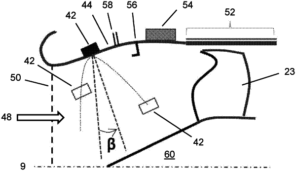
an air flow measurement system including a plurality of acoustic sensors, the plurality of acoustic sensors being disposed upstream of a compressor of the turbomachine, the plurality of acoustic sensors being configured to transmit acoustic waveforms through an intake airflow to a plurality of further acoustic sensors;
a duct defined by an inner circumferential flow surface and an outer circumferential flow surface, the intake airflow flowing between the inner circumferential flow surface and the outer circumferential flow surface; and
an acoustic liner configured to absorb vibrations generated by rotation of a rotor, the acoustic liner being disposed entirely external to the outer circumferential flow surface and outside of the intake airflow, and the plurality of acoustic sensors being located upstream of the acoustic liner, wherein:
the plurality of further acoustic sensors are arranged entirely recessed in the inner circumferential flow surface, the plurality of further acoustic sensors being disposed outside of the intake airflow,
the plurality of acoustic sensors are located in the outer circumferential flow surface in a single plane,
the plurality of further acoustic sensors are configured to communicate with the plurality of acoustic sensors at a point intercepting the single plane, and
the acoustic liner is located upstream of a fan that is positioned at an airflow intake of the turbomachine.
|