| CPC G01L 1/046 (2013.01) [G01L 5/1627 (2020.01); G09B 9/28 (2013.01)] | 14 Claims |

|
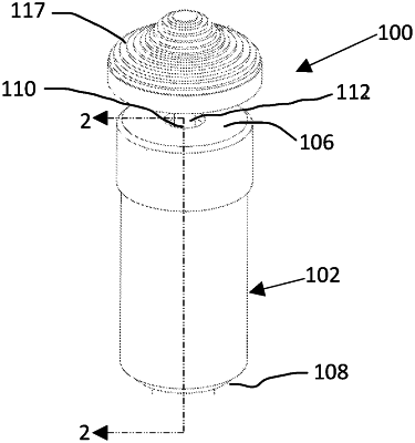
1. A transducer switch comprising:
a housing adapted and configured to allow for mounting of the transducer switch, the housing extending longitudinally between a front and a rear;
a pushbutton switch within the housing and positioned nearer the rear of the housing than the front of the housing;
an input shaft extending from the front of the housing such that an input force can be applied to the input shaft, at least a portion of the input shaft being positioned between the pushbutton switch and the front of the housing, the input shaft comprising:
an input segment having a first diameter and extending longitudinally along a central axis;
a sensing portion, the sensing portion of the input shaft adapted and configured to elastically deform under an input force such that the deformation can be measured and used to provide an input signal to a device corresponding to movement of the input shaft along X and Y axes, the X and Y axes being generally perpendicular to the central axis;
a retaining flange portion extending radially from the central axis of the input shaft and beyond the first diameter, the retaining flange portion adapted and configured to permit the input shaft to be retained longitudinally within the housing of the transducer switch, and the retaining flange portion having a concave radiused shoulder extending radially inward to a second diameter, the second diameter being greater than the first diameter, the concave radiused shoulder also extending longitudinally away from the input segment of the input shaft; and
an end portion extending axially along the central axis and having a rounded terminus, the rounded terminus adapted and configured to tangentially contact the pushbutton switch throughout a range of motion of the input shaft;
a positioning spring located between the retaining flange portion and the rear of the housing, the positioning spring adapted and configured to resist movement of the input shaft in the longitudinal direction toward the rear of the housing, and the positioning spring being adapted and configured to bias the input shaft towards alignment with the central axis; and
a plurality of strain gauges positioned on the sensing portion of the input shaft, the plurality of strain gauges adapted and configured to measure tension and compression on at least two sides of the input shaft, the two sides separated by approximately ninety degrees.
|