| CPC G01F 1/6888 (2013.01) [G01F 1/6847 (2013.01); H10N 10/851 (2023.02); H10N 19/00 (2023.02)] | 19 Claims |

|
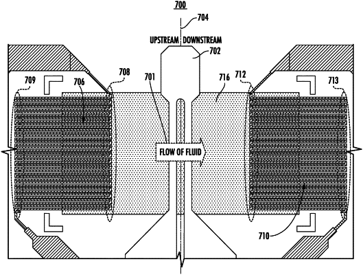
1. An apparatus for sensing a flow of fluid, the apparatus comprising:
a flow sensing device comprising:
a heating structure having a centerline that defines upstream and downstream sections of the flow sensing device;
a membrane structure;
a first thermopile, wherein at least a portion of the first thermopile is disposed over the membrane structure, and wherein the first thermopile comprises:
a first plurality of upstream thermocouple junctions disposed over the membrane structure, and
a second plurality of upstream thermocouple junctions offset from the membrane structure; and
a second thermopile, wherein at least a portion of the second thermopile is disposed over the membrane structure, and wherein the second thermopile comprises:
a first plurality of downstream thermocouple junctions disposed over the membrane structure, and
a second plurality of downstream thermocouple junctions not disposed over the membrane structure,
wherein a maximum temperature difference is defined by a minimum temperature difference location located upstream of the centerline and a maximum temperature difference location located downstream of the centerline,
wherein the maximum temperature difference location and the minimum temperature difference location are based on a temperature profile of the heat generated by the heating structure such that the locations of the maximum temperature difference location and the minimum temperature difference location are defined by at least an applied voltage to the heating structure,
wherein the temperature profile of the heat generated by the heating structure is represented by a temperature isoline,
wherein the temperature isoline has its longest dimension set forth on an x-axis,
wherein the centerline is a vertical centerline and the x-axis is perpendicular to the vertical centerline,
wherein the maximum and minimum temperature difference locations are located at the middle and farthest locations of the temperature isoline of the temperature profile of the heat generated by the heating structure,
wherein the first plurality of upstream thermocouple junctions is aligned substantially parallel to the centerline along an upstream vertical line through about the minimum temperature difference location, and
wherein the first plurality of downstream thermocouple junctions is aligned substantially parallel to the centerline along a downstream vertical line through about the maximum temperature difference location.
|