| CPC G01F 1/6842 (2013.01) [B29C 33/005 (2013.01); G01F 5/00 (2013.01); B29C 45/0025 (2013.01); B29C 66/306 (2013.01); B29C 66/328 (2013.01); B29C 2045/0034 (2013.01)] | 5 Claims |

|
1. An air flow rate measurement device to be installed in a main passage that is configured to cause air to flow therethrough, the air flow rate measurement device comprising:
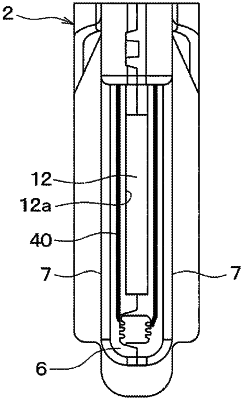
a housing having a front surface on an upstream side of the main passage, a rear surface on a downstream side of the main passage, and a side surface connecting the front surface with the rear surface, the housing formed by injection molding;
a first sub-passage formed in the housing, the first sub-passage communicating a first sub-passage inlet, which is formed in the front surface, with a first sub-passage outlet, which is formed in the rear surface;
a second sub-passage formed in the housing, the second sub-passage communicating a second sub-passage inlet, which is formed in a midway portion of the first sub-passage, with a second sub-passage outlet, which is formed at a position different from the first sub-passage outlet;
a flow rate detection unit provided in the second sub-passage and configured to output a signal according to a flow rate of air flowing through the second sub-passage; and
a mold parting mark formed in the rear surface of the housing at a position that is away from an inner opening edge of the first sub-passage outlet.
|