| CPC F04D 29/441 (2013.01) [F04D 17/10 (2013.01); F04D 29/4213 (2013.01); F04D 29/701 (2013.01)] | 10 Claims |

|
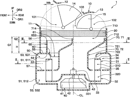
1. A centrifugal blower that is configured to separately suction a first fluid and a second fluid, which are air and have different temperatures or different humidities, respectively, the centrifugal blower comprising:
a fan that is configured to be rotated about a fan axis such that the fan suctions at least one of the first fluid and the second fluid from one side of the fan in an axial direction of the fan axis and outwardly blows the at least one of the first fluid and the second fluid in a radial direction of the fan axis;
a casing that receives the fan; and
a separation tube, at least a portion of which is placed on an inner side of the fan, wherein the separation tube is configured to separately guide the first fluid and the second fluid to the fan in a state where the first fluid and the second fluid are located at an inside and an outside, respectively, of the separation tube, wherein:
the casing has a suction port forming portion that forms a suction port, into which the air is suctioned, wherein the suction port forming portion is formed at one side of the casing in the axial direction;
the separation tube has a tube upper end portion, which forms an air inlet, through which the air flows into the inside of the separation tube;
the tube upper end portion is located on one side of the suction port forming portion in the axial direction such that the tube upper end portion overlaps with a portion of the suction port in the axial direction;
a rib, which projects toward one side in the axial direction, is formed at a periphery of the suction port of the suction port forming portion; and
the periphery of the suction port has:
an overlapping region, which overlaps with the tube upper end portion in the axial direction; and
a non-overlapping region, which does not overlap with the tube upper end portion in the axial direction; and
the rib occupies more area in the non-overlapping region than in the overlapping region.
|