| CPC E21B 43/36 (2013.01) [E21B 43/01 (2013.01); E21B 43/35 (2020.05)] | 10 Claims |

|
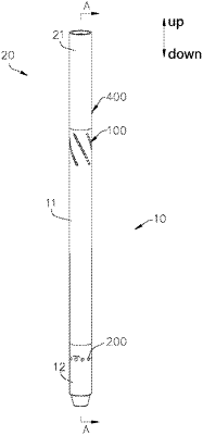
1. A solid fluidization tubular separator for marine natural gas hydrate, comprising
a first separator, wherein the first separator comprises a first separation sleeve, a power liquid pipe, a swirl baffle, a recovery mechanism and a sand discharge mechanism;
the first separation sleeve is provided with a first suction inlet, the first suction inlet is arranged at a middle and upper part of the first separation sleeve, and the first suction inlet is a helical shape;
the power liquid pipe is arranged in the first separation sleeve, and an axis of the power liquid pipe coincides with an axis of the first separation sleeve;
the swirl baffle is arranged on an outer circumference of the power liquid pipe, and there is a gap between the swirl baffle and an inner wall of the first separation sleeve;
the recovery mechanism is arranged above the swirl baffle, the recovery mechanism comprises a recovery sleeve, the recovery sleeve is arranged on the power liquid pipe; a inner diameter of the recovery sleeve is greater than an outer diameter of the power liquid pipe, and an upper part of the recovery sleeve is connected with the first separation sleeve;
the gap between the recovery sleeve and the power liquid pipe forms a hydrate recovery channel;
the sand discharge mechanism is connected to a lower end of the first separation sleeve:
a second separator is further provided, wherein the second separator is connected to an upper end of the first separation sleeve, and the hydrate enters the second separator through the recovery mechanism.
|