| CPC E04H 15/46 (2013.01) [A01M 31/025 (2013.01); E04H 15/001 (2013.01)] | 15 Claims |

|
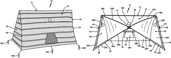
1. A foldable blind comprising:
a fabric front wall having four corners;
a fabric first side wall coupled to the front wall, wherein the fabric first side wall includes an aperture positioned in a top half of the fabric first side wall and wherein a bottom of the first side wall is broader than a top of the first side wall;
a fabric second side wall coupled to the front wall, wherein the fabric second side wall includes an aperture positioned in a top half of the fabric second side wall and wherein a bottom of the second side wall is broader than a top of the second side wall;
an aperture in an upper portion of the front wall;
a hub assembly comprising:
a hub attached to an inner surface of the front wall at a center location of the front wall in both vertical and horizontal directions;
a first rod extending from the hub to a first upper corner of the front wall;
a second rod extending from the hub to second upper corner of the front wall;
a third rod extending from the hub to a first lower corner of the front wall; and
a fourth rod extending from the hub to a second lower corner of the front wall;
four rod pockets, wherein each of the four rod pockets is positioned on the inner surface of the fabric front wall and adjacent one of the four corners of the fabric front wall, each of the four rod pockets being configured to receive an end of one of the four rods;
a first base support coupled to the first sidewall and extending rearward from the first lower corner of the front wall wherein the first base support is positioned along the bottom of the first side wall;
a second base support coupled to the second side wall and extending rearward from the second lower corner of the front wall wherein the second base support is positioned along the bottom of the second side wall;
a first side support coupled to the first side wall and extending between the first upper corner of the front wall and a rear end of the first base support; and
a second side support coupled to the second side wall and extending between the second upper corner of the front wall and a rear end of the second base support.
|