| CPC E04B 1/5818 (2013.01) [E04B 1/40 (2013.01); E04B 2/58 (2013.01); E04B 2001/405 (2013.01)] | 17 Claims |

|
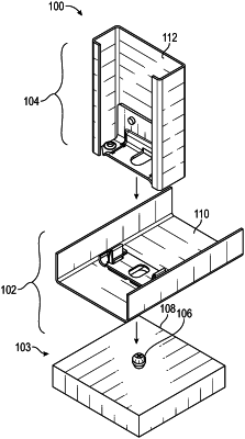
1. A framing system for interconnecting framing components, comprising:
a first connection assembly comprising a first connector, including:
a base defining a first section, a second section, and a center section between the first section and the second section, the base further defining an opening extending through the center section, and
a spring clasp defined along the base, including
a first spring flange defining at least one first spring member and a first retention edge, and
a second spring flange defining at least one second spring member and a second retention edge,
a second connection assembly that engages with the first connection assembly to interconnect the framing components, the second connection assembly comprising a second connector including:
a body defining a first portion, and a second portion along opposite lateral sides of a center portion, a first aperture defined along the first portion, and a second aperture defined along the second portion,
a first spring tab defined along the first aperture, and
a second spring tab defined along the second aperture;
wherein in a first locked configuration, the first connection assembly receives a fastener through the opening, the fastener engages the first and second retention edges and deflects the first and second spring flanges temporarily away from an original configuration, the first and second spring flanges biased to return to the original configuration to lock the first and second retention edges along the fastener,
wherein in a second locked configuration, the second connection assembly is positioned over the first connection assembly such that the first tab and the second tab engage a locking arrangement defined along the spring clasp thereby interconnecting the first connection assembly to the second connection assembly.
|