| CPC B62D 5/0484 (2013.01) [H02P 27/06 (2013.01)] | 18 Claims |

|
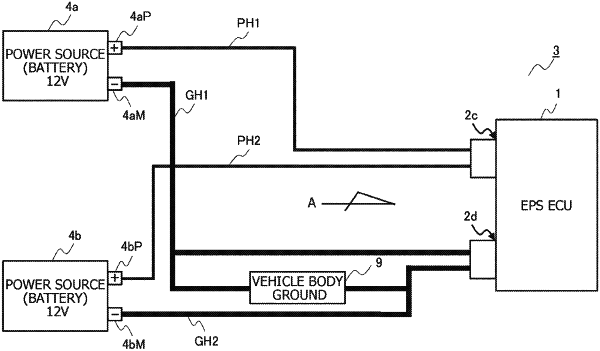
1. A control device for an on-board device to be installed in a vehicle, the on-board device including an actuator and supplied with power by a first power source and a second power source,
the control device comprising:
a housing having an electronic device housing space;
a first connector portion provided to the housing and having a first positive terminal and a second positive terminal,
wherein the first positive terminal is adapted to be connected to a positive electrode of the first power source, and
wherein the second positive terminal is adapted to be connected to a positive electrode of the second power source;
a second connector portion provided to the housing separately from the first connector portion and having a first negative terminal and a second negative terminal,
wherein the first negative terminal is adapted to be connected to a negative electrode of the first power source or a vehicle grounding member, and
wherein the second negative terminal is adapted to be connected to a negative electrode of the second power source or the vehicle grounding member;
a ground portion formed of an electrically conductive material and housed in the electronic device housing space;
a first driver circuit housed in the electronic device housing space and connected between the ground portion and the positive electrode of the first power source,
wherein the first driver circuit is supplied with power from the first power source, and includes a first inverter configured to drive and control the actuator;
a second driver circuit housed in the electronic device housing space and connected between the ground portion and the positive electrode of the second power source,
wherein the second driver circuit is supplied with power from the second power source, and includes a second inverter configured to drive and control the actuator; and
a processor housed in the electronic device housing space and including a first microprocessor and a second microprocessor,
wherein the first microprocessor is supplied with power from the first power source and is configured to output a first command signal for controlling the first inverter,
wherein the second microprocessor is supplied with power from the second power source and is configured to output a second command signal for controlling the second inverter,
wherein a current capacity of the first negative terminal is greater than a current capacity of the first positive terminal, and
wherein a current capacity of the second negative terminal is greater than a current capacity of the second positive terminal.
|