| CPC B61L 1/181 (2013.01) [H02B 1/012 (2013.01); H02B 1/0523 (2013.01); H02B 1/205 (2013.01); H02B 11/02 (2013.01)] | 18 Claims |

|
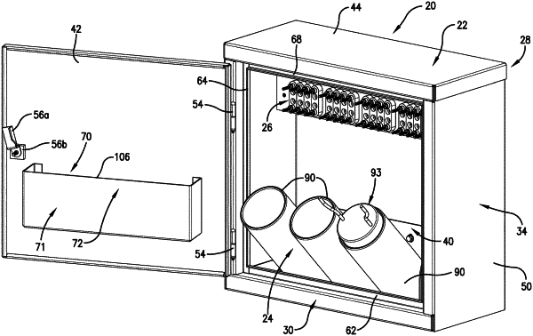
1. A railway shunt enclosure comprising:
an outer wall defining an interior space;
a receptacle configured to receive a shunt; and
a connector assembly including a first portion fixed relative to the outer wall and a rotatable second portion fixed relative to the receptacle, such that the receptacle is rotatable between a retracted position, wherein the receptacle is positioned within the interior space, and a protruded position, wherein at least a portion of the receptacle protrudes from the interior space,
one of said portions of the connector assembly including a pin, and the other of said portions of the connector assembly including a first knuckle rotatably received on the pin,
said pin being fixedly coupled relative to the outer wall,
said first knuckle being fixed to the receptacle,
said connector assembly including a second knuckle configured to maintain lateral separation between the outer wall and the first knuckle,
said second knuckle being received on the pin.
|