| CPC B60Q 1/0491 (2013.01) [B60Q 1/0441 (2013.01); F21S 41/196 (2018.01)] | 15 Claims |

|
1. A impact-absorbing vehicle headlamp system (1), comprising:
at least one vehicle frame element (2) that can be firmly connected to a vehicle,
a vehicle headlamp housing (3) that is displaceably held on the vehicle frame element (2), having at least one pin (4) connected to the vehicle headlamp housing (3), wherein the vehicle frame element (2) comprises at least one guide (2a) for receiving and linearly guiding the pin (4), wherein the pin (4) is in engagement with the guide (2a) so that the vehicle headlamp housing (3) is guided by the displacement of the pin (4) along the guide (2a) and thus displaceable with respect to the vehicle frame element (2),
at least one triggering element (5) that can be mechanically connected to a bumper of a vehicle, and
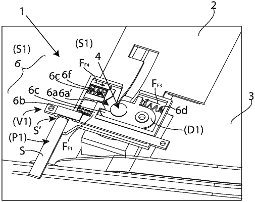
at least one triggering mechanism (6) that is firmly connected to the vehicle frame element (2), which is equipped in order to receive the triggering element (5) and the pin (4) and to change at least as a function of the position of the triggering element (5), between a state (S1) blocking the pin (4) and a state (S2) releasing the pin (4), wherein in the state (S2) releasing the pin (4) the vehicle headlamp housing (3) including the pin (4) can be displaced with respect to the vehicle frame element (2),
wherein the triggering mechanism (6) comprises:
a pivot arm (6a) that is pivotably mounted in the triggering mechanism (6), which pivot arm (6a) comprises an engagement region (6a′) for receiving the pin (4), wherein the pivot arm (6a) is equipped in order to be rotated between two positions, namely between a holding position (D1), in which the pivot arm (6a) counteracts a movement of a pin (4) received in the engagement region (6a′) along the guide (2a) and a release position (D2), in which the pivot arm (6a) releases the movement of the pin (4) along the guide (2a),
a locking element (6b), which is linearly displaceably held in the triggering mechanism (6), wherein the locking element (6b) is equipped in order to engage in the pivot arm (6a) in the blocking position (D1), and lock the same as a function of the position of the triggering element (5) in the said blocking position (D1) or release a change into the release position (D2), in that the locking element (6b) is displaceable between a locking position (V1) for blocking the pivot arm (6a) and an unlocking position (V2) for releasing the change of the pivot arm (6a) into the release position (D2), wherein a first spring element (6c) is provided, which exerts on the locking element (6b) a spring force (FF1) pushing the same into the locking position (V1), wherein the locking element (6b) is mechanically coupled to the triggering element (5) in such a manner that in a starting position (P1) of the triggering element (5) the locking element (6b) is held in the locking position (V1) with the help of the first spring element (6c), and that as a consequence of a displacement of the position of the triggering element (5) into a release position (P2), the locking element (6b) is displaced against the spring force (FF1) into the unlocking position (V2), so that a rotation of the pivot arm (6a) from the holding position (D1) towards the release position (D2) is made possible, and the triggering mechanism (6) thus changes into the releasing state (S2).
|