| CPC B60N 2/067 (2013.01) [B60N 2/0232 (2013.01); B60N 2/0705 (2013.01); B60N 2/929 (2018.02); B60N 2002/0236 (2013.01); B60N 2205/20 (2013.01)] | 6 Claims |

|
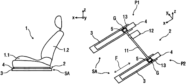
1. A longitudinal adjuster for a vehicle seat, comprising:
a rail arrangement having two rail pairs of seat rails, wherein the respective rail pair has a fixed seat rail and a seat rail which is movable relative to the fixed seat rail,
a motor unit,
a gear unit which couples the motor unit and the movable seat rail of at least one of the rail pairs to each other, and
a retention member for receiving a gear housing of the gear unit,
wherein the retention member is arranged with the gear unit in a hollow space formed by one rail pair and is secured to the movable seat rail thereof, and is constructed to be open at one end and closed at the opposite end, and
wherein the retention member is constructed as a U-shaped profile,
wherein the U-shaped profile has two planar retention legs, wherein the planar retention legs are equally spaced apart by a planar connector such that the planar retention legs extend transverse the connector, and
wherein a U-shaped reinforcement element comprised of a planar base section connecting two planar and equally spaced apart clamp legs generally extending transverse the base section is adapted to at least partially and selectively nest about the retention legs, wherein outside surfaces of both clamp legs are located adjacent and generally parallel outside surfaces of the retention legs and wherein a bottom portion of each retention leg is located adjacent and generally parallel an upper surface of the base section,
wherein the base section extends parallel the planar connector,
wherein both retention member legs and both reinforcement element clamp legs together define an aligned spindle opening adapted to receive a spindle through all the legs.
|