| CPC B60L 13/10 (2013.01) [B60B 19/006 (2013.01); B61B 13/08 (2013.01); B60L 2200/26 (2013.01)] | 4 Claims |

|
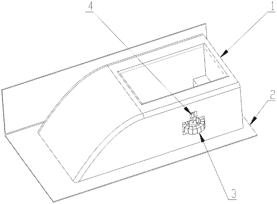
1. A magnetic levitation (maglev) train driving method based on a magnetic wheel driving device, the magnetic wheel driving device comprising a vehicle body, a guide rail system, at least two magnetic wheel systems and a power system; the guide rail system comprising two conductor plates; one of the two conductor plates being arranged at a first side of the vehicle body, and the other of the two conductor plates being arranged at a second side of the vehicle body; the at least two magnetic wheel systems being symmetrically arranged at two side walls of the vehicle body; a gap being provided between each of the at least two magnetic wheel systems and a corresponding conductor plate of the two conductor plates; the power system being configured to drive the at least two magnetic wheel systems to rotate; each of the at least two magnetic wheel systems comprising a wheel hub and a permanent magnetic wheel; the wheel hub being arranged parallel to ground; an inner ring of the wheel hub being rotatably connected to the vehicle body; the permanent magnetic wheel being arranged on an outer ring of the wheel hub; the guide rail system having a U-shaped structure; the guide rail system further comprising a rail; the rail being arranged parallel to the ground; the two conductor plates being perpendicular to the ground, and being arranged respectively at two sides of the rail; the power system comprising two motors and a transmission assembly; the two motors being arranged inside the vehicle body; the two motors being connected to the at least two magnetic wheel systems through the transmission assembly; among the at least two magnetic wheel systems, a magnetic wheel system at one side wall of the vehicle body having a rotation direction opposite to that of a magnetic wheel system at the other side of the vehicle body; one of the two motors being opposite to the other of the two motors in rotation direction; the transmission assembly being a transmission shaft; one end of the transmission being fixedly connected to an output shaft of each of the motors; and the other end of the transmission shaft being fixedly connected to each of the at least two magnetic wheel systems; and the maglev train driving method comprising:
(a) receiving a first control command, wherein the first control command comprises a command for controlling the power system to start;
(b) sending a second control command in response to the first control command, wherein the second control command comprises a command for energizing the power system; and after the power system is energized, driving the at least two magnetic wheel systems to rotate; wherein during rotation, the at least two magnetic wheel systems act together with the two conductor plates to generate a driving force to drive the vehicle body to move;
(c) detecting a speed of the vehicle body; if the speed reaches a preset speed, sending a third control command, wherein the third control command comprises a command for adjusting a rotation speed of the at least two magnetic wheel systems to allow the vehicle body to make a uniform motion at the preset speed; and
(d) detecting a distance between a position of the vehicle body and a preset deceleration point; if the vehicle body reaches the preset deceleration point, sending a fourth control command, wherein the fourth control command comprises a command for reducing the rotation speed of the at least two magnetic wheel systems to a preset rotation speed to stop the vehicle body at a preset stop point;
wherein step (c) further comprises:
adjusting the rotation speed of the at least two magnetic wheel systems to accelerate the vehicle body to the preset speed;
the vehicle body is accelerated through steps of:
adjusting the rotation speed of the at least two magnetic wheel systems such that an equivalent linear speed of each of the at least two magnetic wheel systems is greater than a horizontal motion speed of the vehicle body, wherein rotation of the permanent magnet wheel allows each of the two conductor plates to generate an induced eddy current; the induced eddy current generates a mirror-image magnetic field having an opposite direction to a rotating magnetic field of the permanent magnet wheel; the mirror-image magnetic field and the rotating magnetic field together generate the driving force to make the vehicle body in an acceleration state; and
the uniform motion of the vehicle body is performed through steps of:
adjusting the rotation speed of the at least two magnetic wheel systems such that the equivalent linear speed of each of the at least two magnetic wheel systems is equal to the horizontal motion speed of the vehicle body, wherein in this case, the driving force generated by the mirror-image magnetic field and the rotating magnetic field is zero, thereby realizing the uniform motion of the vehicle body.
|