| CPC B60L 13/04 (2013.01) [B60G 17/015 (2013.01); F16F 15/03 (2013.01); B60G 2202/16 (2013.01); B60G 2600/22 (2013.01)] | 1 Claim |

|
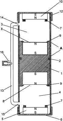
1. A magnetic suspension stabilizer comprising, a tubular body;
an air flow duct;
a piston;
one upper piston magnetic;
one lower piston magnetic;
two piston seals;
one upper cover;
one lower cover;
one upper cover magnet;
one lower cover magnet;
one air flow valve;
the piston is arranged within the tubular body separating inside of the tubular body into chamber A and chamber B;
each of the two piston seals is fixed to the piston at opposite sides of the piston;
each of the two piston seals separates the chamber A and chamber B;
the upper piston magnet is fixed to the piston at one end of the piston within the chamber A;
the lower piston magnet is fixed to the piston within the chamber B;
the tubular body comprises an upper end and a lower end;
the upper cover seals the upper end of the tubular body;
the upper cover magnet is fixed to the upper cover, wherein the upper cover magnet is positioned inside of the tubular body;
the upper cover magnet comprises a predetermined magnetic pole UCS and an opposite magnetic pole UCN, wherein the polarity of UCS is opposite of the polarity of the UCN;
the upper cover magnet is fixed to the upper cover by the UCS, wherein the polarity of UCN is facing toward the piston within the chamber A;
two washers are fixed to the UCN;
the lower cover seals the lower end of the tubular body;
the lower cover magnet is fixed to the lower cover, wherein the lower cover magnet is positioned inside of the tubular body;
the lower cover magnet comprises a predetermined magnetic pole LCS and an opposite magnetic pole LCN;
the lower cover magnet is fixed to the lower cover by the LCS, wherein the LCN is facing toward the piston within the chamber B;
two washers are fixed to the LCN;
the upper piston magnet having a predetermined magnetic pole UPN and an opposite magnetic pole UPS;
the upper piston magnet is positioned in a direction wherein the UPN faces the UCN in the chamber A;
two washers lock the upper piston magnet to the piston;
the lower piston magnet has a predetermined magnetic pole LPN and an opposite magnetic pole LPS;
the lower piston magnet is positioned in a direction wherein the LPN faces the LCN in the chamber B;
two washers lock the lower piston magnet to the piston; and
the air flow duct connects the chamber A and the chamber B via the air flow valve.
|