| CPC B41J 2/17509 (2013.01) [B41J 2/1754 (2013.01); B41J 2/17513 (2013.01); B41J 2/17553 (2013.01); B41J 2/17566 (2013.01); B41J 2/17596 (2013.01)] | 15 Claims |

|
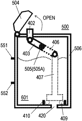
1. An ink tank configured to supply liquid to an apparatus having a liquid consumption device, the ink tank comprising:
a first liquid storage chamber configured to store liquid, the first liquid chamber comprising a visual recognition portion having a lower limit indicator indicating a liquid level height prompting a user to inject liquid;
a second liquid storage chamber connected to the first liquid storage chamber through a communication passage, the second liquid storage chamber having a liquid supply port supplying liquid to the liquid consumption device;
a liquid inlet which communicates with the first liquid storage chamber;
a cap openable or closeable with respect to the liquid inlet;
a rotation shaft extending from an inside of the first liquid storage chamber to an outside of the ink tank through a through hole, the through hole being provided on a side wall of the first liquid storage chamber;
a valve member provided in the first liquid storage chamber, the valve member being moveable so as to open or close the communication passage;
a first lever arm rotatable around the rotation shaft as a center of rotation in the first liquid storage chamber, the first lever arm being connected to the valve member;
a second lever arm provided outside the ink tank, the second lever arm being rotatable around the rotation shaft as the center of rotation; and
a slider member provided outside the ink tank and connected to the second lever arm, the slider member being movable in an up-down direction in conjunction with an opening and closing operation of the cap,
wherein the through hole is provided at a position above the lower limit indicator.
|