| CPC B29C 66/73921 (2013.01) [B23K 26/064 (2015.10); B29C 65/1612 (2013.01); B29C 65/1635 (2013.01); B29C 65/1667 (2013.01); B29C 65/1687 (2013.01); B29C 66/12443 (2013.01); B29C 66/12461 (2013.01); B29C 66/12463 (2013.01); B29C 66/12469 (2013.01); B29C 66/54 (2013.01); G02B 6/10 (2013.01); G02B 6/4296 (2013.01); B29C 66/8322 (2013.01)] | 11 Claims |

|
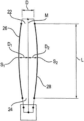
1. Method for plastic welding with an arrangement comprising a laser light source, a light guide and a waveguide, wherein the waveguide is a negative waveguide comprising an entry end defining an entry face for laser light, an exit end defining an exit face for laser light as well as a first and a second inner face which are arranged between the entry end and the exit end, which are arranged opposite to each other and by means of which laser light can be reflected, wherein a first distance between the entry end and the exit end defines a length of the waveguide and a cavity is present between the first and the second inner face through which laser light is guidable, and a second distance between the first and the second inner face defines a thickness of the waveguide, wherein the waveguide further realizes one of the following features:
i) the exit end is arranged opposite to the entry end and a central plane of the waveguide extends centrally from the entry end to the exit end, and the first inner face comprises a continuously curved, concave shape so that a third distance between the first inner face and the central plane of the waveguide varies continuously from the entry end in the direction of the exit end, in which the third distance increases from the entry end in the direction of the exit end up to an apex and decreases thereafter and the continuously curved concave shape of the first inner face is part of an ellipse, or
ii) the first inner face comprises a continuously curved concave shape which is part of a first spiral so that a radius of the first spiral from a point of origin of the first spiral to the first inner face varies continuously along the waveguide, the second inner face comprises a continuously curved convex shape which is part of a second spiral, so that a radius of the second spiral from a point of origin of the second spiral to the second inner face varies continuously along the waveguide, wherein the thickness of the waveguide decreases continuously from the entry end in the direction of the exit end and an angle in the range of 30° to 150° is enclosed between the entry end and the exit end wherein the method comprises the following steps:
a. arranging two plastic components to be welded to each other in a mounting device,
b. creating laser light by means of the laser light source, wherein the laser light passes through the light guide, and subsequently through the waveguide, and
c. welding the plastic components to be welded to each other by means of the laser light exiting the waveguide.
|