| CPC B21B 37/28 (2013.01) [G06F 30/23 (2020.01); G06F 30/25 (2020.01); G06F 30/367 (2020.01); G06F 30/398 (2020.01); G06F 2111/00 (2020.01); G06F 2119/22 (2020.01)] | 2 Claims |

|
1. A strip flatness prediction method considering lateral spread during rolling, comprising the following steps:
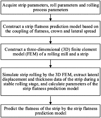
step 1: acquiring strip parameters, roll parameters and rolling process parameters, wherein the strip parameters comprise strip width, thickness, crown ratio, density, elastic modulus, yield strength, Poisson's ratio and tangent modulus; the roll parameters comprise diameter, barrel length, density, elastic modulus and Poisson's ratio of a work roll; the rolling process parameters comprise friction and rolling speed;
step 2: constructing a strip flatness prediction model based on coupling of flatness, crown and lateral spread by considering lateral metal flow;
step 3: constructing a three-dimensional (3D) finite element model (FEM) of a rolling mill and a strip according to the strip parameters, the roll parameters and the rolling process parameters, simulating strip rolling by the 3D FEM, extracting lateral displacement and thickness data of the strip during a stable rolling stage, and calculating parameters of the strip flatness prediction model based on the coupling of flatness, crown and lateral spread; and
step 4: predicting the flatness of the strip by the strip flatness prediction model based on the coupling of flatness, crown and lateral spread,
wherein step 2 comprises the following steps:
step 2.1: constructing a coordinate system for the strip by taking a center of the strip as an origin of coordinates and width, length and thickness directions as 3D coordinate axes; regarding the strip before rolling as an entity of continuous longitudinal fiber strips; taking a longitudinal fiber strip at a widthwise position with a distance y from a center of the strip, and defining width, thickness and length of the longitudinal fiber strip before rolling as dy, H(y) and L(y) respectively; increasing the width of the longitudinal fiber strip after rolling to dy+[u(y+dy)−u(y)], reducing the thickness of the longitudinal fiber strip after rolling to h(y), and increasing the length of the longitudinal fiber strip after rolling to l(y), by considering lateral flow of metal particles during the strip rolling, wherein u(y) represents a lateral displacement function of metal particles of the strip;
step 2.2: constructing the strip flatness prediction model based on the coupling of flatness, crown and lateral spread:
step 2.2.1: according to a principle of constant volume before and after rolling:
h(y)·l(y)·[dy+u(y+dy)−u(y)]=H(y)·L(y)·dy (1)
deriving the length of the longitudinal fiber strip after rolling as:
 where u′(y) represents a derivative function of the lateral displacement function u(y);
step 2.2.2: determining a reference length for all longitudinal fiber strips of the strip after rolling;
 where y represents a distance of a reference longitudinal fiber strip from the center of the strip; l(y) represents a length of the reference longitudinal fiber strip after rolling; H(y) represents a thickness of the reference longitudinal fiber strip before rolling; L(y) represents a length of the reference longitudinal fiber strip before rolling; h(y) represents a thickness of the reference longitudinal fiber strip after rolling;
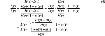
step 2.2.3: calculating a length ratio of any longitudinal fiber strip with the distance of y from the center of the strip to the reference longitudinal fiber strip after rolling:
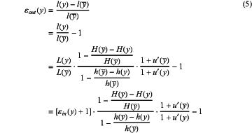
 step 2.2.4: calculating a longitudinal strain of the longitudinal fiber strip with the distance of y from the center of the strip after rolling as εout(y):
 where εin(y) represents a longitudinal strain before rolling,
 step 2.2.5: defining a change factor of a lateral thickness difference before and after rolling as Cr:
 defining a lateral spread factor as Tf:
 obtaining the longitudinal strain of the longitudinal fiber strip after rolling as:
εout(y)=[εin(y)+1]·Cr·Tf−1 (8)
step 2.2.6: calculating an outlet flatness of the strip as Iout(y):
Iout(y)=εout(y)/10−5 (9)
step 2.2.7: calculating a total residual tensile stress by regarding an elastic deformation of the strip caused by a tension as a plane deformation as σxx_totalout(y):
σxx_totalout(y)=σout+σxxout(y) (10)
where σout represents an outlet reference tensile stress, and σxxout(y) represents a longitudinal residual tensile stress caused by an uneven extension of the longitudinal fiber;
 then
 where E and v respectively represent the elastic modulus and Poisson's ratio of the strip;
step 2.2.8: obtaining the strip flatness prediction model based on the coupling of flatness, crown and lateral spread as:
 where Iin(y) represents an inlet flatness of the strip.
|