| CPC B05B 17/0607 (2013.01) [B05B 5/16 (2013.01)] | 6 Claims |
|
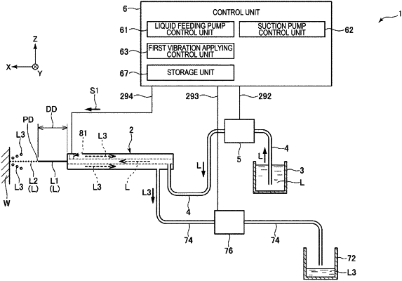
1. A liquid ejection device comprising:
a liquid feeding pump configured to supply a liquid to a nozzle at a predetermined pressure, the liquid feeding pump being connected to a liquid supplying tube
a liquid conveying tube connected to the liquid supplying tube and configured to convey the liquid from the liquid feeding pump to the nozzle, the nozzle being provided at an end of the liquid conveying tube, the nozzle being configured to eject the liquid therefrom to an outside as an ejected liquid flow;
an outer tube that is internally provided with the nozzle and the liquid conveying tube, the outer tube having a suction channel therein, the suction channel circumscribing the liquid conveying tube, the suction channel being connected to a suction pump via a suction tube; and
a second piezoelectric device configured to apply vibration to the nozzle or the liquid conveying tube so as to transfer the vibration to the ejected liquid flow, wherein
a first piezoelectric device disposed directly adjacent to the nozzle, the first piezoelectric device being configured to apply vibration to the nozzle and the liquid conveying tube so as to transfer the vibration to the ejected liquid flow, wherein
the first piezoelectric device spans between an inner surface of the outer tube and one of an outer surface of the nozzle or an outer surface of the liquid conveying tube,
the suction channel is configured to suck part of the liquid of the ejected liquid flow,
the first piezoelectric device is configured to generate the vibration in a first axial direction intersecting an axis of the liquid conveying tube, and
the second piezoelectric device is configured to generate the vibration in a second axial direction intersecting the axis of the liquid conveying tube and different from the first axial direction.
|