| CPC A61F 2/447 (2013.01) [A61F 2/28 (2013.01); A61F 2/4455 (2013.01); A61F 2/4465 (2013.01); A61F 2/4601 (2013.01); A61F 2/4611 (2013.01); A61F 2002/2817 (2013.01); A61F 2002/30092 (2013.01); A61F 2002/30133 (2013.01); A61F 2002/30168 (2013.01); A61F 2002/30304 (2013.01); A61F 2002/30405 (2013.01); A61F 2002/30471 (2013.01); A61F 2002/30507 (2013.01); A61F 2002/30537 (2013.01); A61F 2002/30538 (2013.01); A61F 2002/30556 (2013.01); A61F 2002/30579 (2013.01); A61F 2002/30593 (2013.01); A61F 2002/30841 (2013.01); A61F 2002/448 (2013.01); A61F 2002/4627 (2013.01); A61F 2002/4629 (2013.01); A61F 2310/00017 (2013.01); A61F 2310/00023 (2013.01); A61F 2310/00029 (2013.01); A61F 2310/00293 (2013.01); A61F 2310/00359 (2013.01); A61F 2310/00407 (2013.01); A61F 2310/00796 (2013.01); A61F 2310/00976 (2013.01); B33Y 80/00 (2014.12)] | 20 Claims |
|
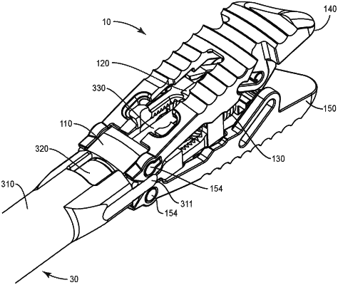
1. An expandable spinal implant comprising:
a frame comprising a frame proximal end, an opposite frame distal end, a distal wall at the frame distal end, and a distal aperture defined in the distal wall;
a plug movably disposed in the distal aperture and configured for movement from a first position to a second position, the plug including a head portion including at least a first lateral post portion and a second lateral post portion;
a first endplate portion pivotally engaged with the frame and configured to expand outward from the frame when the plug is moved from the first position to the second position, the first endplate portion including an upper surface, a first endplate portion proximal end, a first endplate portion distal end, at least one of a first endplate portion first lateral surface extending between the first endplate portion proximal end and the first endplate portion distal end and an opposing first endplate portion second lateral surface extending between the first endplate portion proximal end and the first endplate portion distal end, and a first channel formed in the at least one of the first endplate portion first lateral surface and the second endplate portion second lateral surface, the first channel being configured to receive one of the first lateral post portion and the second lateral post portion;
a first distal end portion extending outwardly from the first endplate portion including at least one side surface and a first tip portion, the at least one side surface of the first distal end portion extending from the first tip portion to the at least one of the first endplate portion first lateral surface and the first endplate portion second lateral surface;
a second endplate portion pivotally engaged with the frame and configured to expand outward from the frame when the plug is moved from the first position to the second position, the second endplate portion including a lower surface, a second endplate portion proximal end, a second endplate portion distal end, at least one of a second endplate portion first lateral surface extending between the second endplate portion proximal end and the second endplate portion distal end and an opposing second endplate portion second lateral surface extending between the second endplate portion proximal end and the second endplate portion distal end, and a second channel formed in the at least one of the second endplate portion first lateral surface and the second endplate portion second lateral surface, the second channel being configured to receive the other of the first lateral post portion and the second lateral post portion;
a second distal end portion extending outwardly from the second endplate portion including at least one side surface and a second tip portion, the at least one side surface of the second distal end portion extending from the second tip portion to the at least one of the second endplate portion first lateral surface and the second endplate portion second lateral surface;
wherein movement of the plug from the first position to the second position, and corresponding interaction of the one of the first lateral post portion and the second lateral post portion in the first channel causes the first endplate portion and the first distal end portion to move away from the frame and interaction of the other of the first lateral post portion and the second lateral post portion in the second channel causes the second endplate portion and the second distal end portion to move away from the frame to move the implant from a collapsed position to an expanded position; and
wherein the first distal end portion includes a mid-longitudinal axis that is transverse to a mid-longitudinal axis of the first endplate portion, and the second distal end portion includes a mid-longitudinal axis that is transverse to a mid-longitudinal axis of the second endplate portion.
|