| CPC A61F 2/28 (2013.01) [A61B 17/885 (2013.01); A61F 2/30771 (2013.01); A61F 2/44 (2013.01); A61F 2/4611 (2013.01); A61F 2/4657 (2013.01); A61B 2017/0046 (2013.01); A61B 2017/00473 (2013.01); A61B 2017/0256 (2013.01); A61B 2090/061 (2016.02); A61F 2/4425 (2013.01); A61F 2002/2835 (2013.01); A61F 2002/305 (2013.01); A61F 2002/30224 (2013.01); A61F 2002/30235 (2013.01); A61F 2002/30387 (2013.01); A61F 2002/30604 (2013.01); A61F 2002/30774 (2013.01); A61F 2002/30818 (2013.01); A61F 2002/30828 (2013.01); A61F 2002/30836 (2013.01); A61F 2002/30878 (2013.01); A61F 2002/443 (2013.01); A61F 2002/4615 (2013.01); A61F 2002/4658 (2013.01)] | 24 Claims |

|
1. A spinal implant replacement instrument kit, comprising:
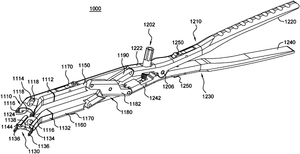
a distraction instrument; and
a spinal implant, wherein the spinal implant comprises an intermediate spacer comprising a longitudinal axis, an outer surface, and a first end and a second end, wherein the distance between the first and second ends defines a length of the intermediate spacer;
a first member removably coupled to the first end of the intermediate spacer; and
a second member removably coupled to the second end of the intermediate spacer, wherein the intermediate spacer further comprises:
a gap on a first side extending from the first end to the second end; wherein the gap extends from the outer surface into a central bore of the intermediate spacer;
an instrument coupling mechanism comprising at least one groove extending on a third side of the intermediate spacer, wherein the at least one groove extends along a lateral direction from the first side to a second side; and
a first planar outer surface portion positioned on the third side and a second planar outer surface portion positioned on a fourth side of the intermediate spacer outer surface, wherein the fourth side is opposite the third side, wherein the first and second planar outer surface portions are positioned between the first end and the instrument coupling mechanism;
a first coupling mechanism on the first end of the intermediate spacer for engaging a coupling mechanism of a first member; and
a second coupling mechanism on the second end of the intermediate spacer for engaging a coupling mechanism of a second member.
|