US 11,744,645 B2
Surgical tool with a two degree of freedom wrist
William A. Burbank, Sandy Hook, CT (US)
Assigned to Intuitive Surgical Operations, Inc., Sunnyvale, CA (US)
Filed by Intuitive Surgical Operations, Inc., Sunnyvale, CA (US)
Filed on Jul. 13, 2021, as Appl. No. 17/374,014.
Application 16/028,888 is a division of application No. 14/485,427, filed on Sep. 12, 2014, granted, now 10,045,823, issued on Aug. 14, 2018.
Application 14/485,427 is a division of application No. 12/945,748, filed on Nov. 12, 2010, granted, now 8,852,174, issued on Oct. 7, 2014.
Application 17/374,014 is a continuation of application No. 16/028,888, filed on Jul. 6, 2018, granted, now 11,090,119.
Claims priority of provisional application 61/260,903, filed on Nov. 13, 2009.
Claims priority of provisional application 61/260,915, filed on Nov. 13, 2009.
Claims priority of provisional application 61/260,910, filed on Nov. 13, 2009.
Prior Publication US 2021/0338332 A1, Nov. 4, 2021
This patent is subject to a terminal disclaimer.
Int. Cl. A61B 17/00 (2006.01); F16D 3/26 (2006.01); A61B 34/10 (2016.01); A61B 34/00 (2016.01); A61B 34/30 (2016.01); A61B 34/37 (2016.01); F16D 3/18 (2006.01); A61B 17/064 (2006.01); A61B 17/28 (2006.01); A61B 17/285 (2006.01)
CPC A61B 34/10 (2016.02) [A61B 17/00234 (2013.01); A61B 17/064 (2013.01); A61B 17/28 (2013.01); A61B 17/285 (2013.01); A61B 34/30 (2016.02); A61B 34/37 (2016.02); A61B 34/71 (2016.02); F16D 3/185 (2013.01); F16D 3/26 (2013.01); A61B 2017/00526 (2013.01); A61B 2034/305 (2016.02); Y10S 901/29 (2013.01); Y10T 29/49826 (2015.01)] 16 Claims
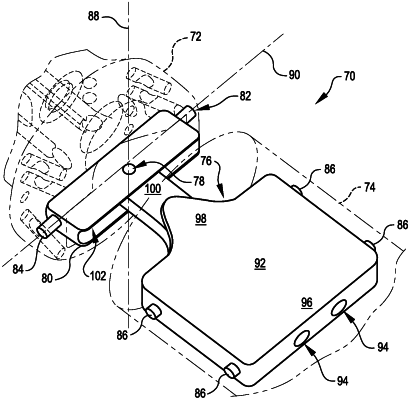
OG exemplary drawing
 
1. A minimally invasive surgical tool comprising:
an instrument shaft elongated along an instrument shaft axis;
a drive shaft mounted to the instrument shaft for rotation about a drive shaft axis;
an end effector coupled with the instrument shaft so that an orientation of the end effector can be varied relative to the instrument shaft;
a driven shaft coupled with the end effector to articulate a feature of the end effector via rotation of the driven shaft relative to the end effector; and
a coupling member coupling the drive shaft with the driven shaft so that a rate of rotation of the drive shaft and a rate of rotation of the driven shaft about a driven shaft axis are equal when the drive shaft axis and the driven shaft axis are non-parallel.