| CPC A61B 18/1442 (2013.01) [A61B 18/085 (2013.01); A61B 2018/00589 (2013.01); A61B 2018/00595 (2013.01); A61B 2018/146 (2013.01); A61B 2018/1462 (2013.01); A61B 2018/167 (2013.01)] | 17 Claims |

|
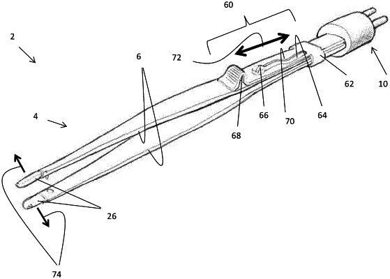
1. A forceps comprising:
a first working arm having a first distal end and a first proximal end, the first distal end including a first tip, a first contact surface, a first connection surface opposite the first tip, and a first rotation axis;
a second working arm having a second distal end and a second proximal end, the second distal end including a second tip, a second contact surface, a second connection surface opposite the second tip, and a second rotation axis;
a skewing region defined at the proximal ends of the first and second working arms, the skewing region including a skewing pathway;
a pin at least partially receivable within the skewing pathway; and
a skewing device located at the skewing region;
wherein the skewing device is configured to move longitudinally along the skewing region such that the pin guides the skewing device along the skewing pathway to apply a lateral force, a rotational force or a combination of both to the first and second working arms and move the forceps between a first position, a second position and a third position;
wherein in the first position, the first contact surface is substantially opposite and facing toward the second contact surface so that the first and second working arms can be used to grip an item therebetween;
wherein the skewing device is configured to move the first and second working arms between the first and second positions such that the skewing device applies a lateral force to the working arms to askew the first tip with respect to the second tip, wherein the lateral force causes a planar motion of at least one of the first tip or the second tip;
wherein the skewing device is configured to move the first and second working arms between the first and third positions by applying a rotational force to the working arms, wherein the first and second working arms are configured to rotate about the first and second rotation axes, respectively; and
wherein in the third position, the first connection surface is in direct contact with the second connection surface, and the first tip and the second tip each form an edge on opposing sides of the forceps.
|