| CPC A43C 11/165 (2013.01) [A43C 11/146 (2013.01)] | 8 Claims |

|
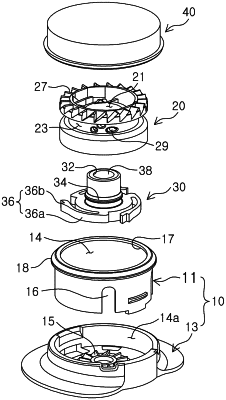
1. A wire tightening device comprising:
a housing in which an inner space is formed and locking teeth are formed at a bottom portion thereof;
a winding wheel located in the inner space of the housing, and having a through hole vertically formed in the middle thereof, a winding groove which is formed on the outer circumferential surface of the through hole and on which a wire is wound, a first ratchet part mounted on the inner circumferential surface of the through hole and below the winding groove, and coupling teeth formed at the upper portion thereof;
a lifting member disposed in the through hole of the winding wheel, and having a second ratchet part disposed at a lower portion thereof and engaged with the first ratchet part to allow rotation in one direction and prevent rotation in the other direction with respect to the winding wheel, and engagement teeth formed at a lower end portion thereof to be caught to the locking teeth; and
a tightening cap coupled to the upper portion of the housing in a liftable manner, having tightening teeth coupled with the coupling teeth when lowering to rotate the winding wheel in the winding direction of the wire, and coupled with the lifting member to perform a lifting motion together with the lifting member,
wherein the through hole is divided into an upper through hole and a lower through hole which is larger in diameter than the upper through hole, and the first ratchet part is formed along the circumference of the lower through hole,
wherein the first ratchet part includes ratchet teeth formed on the circumference there of to be inclined in one direction, and
wherein a plurality of the second ratchet parts are fixed on the circumference of the lifting member in a vortex shape, and include ratchet blades disposed at a free end thereof and having ratchet blade teeth ratchet-coupled with the ratchet teeth of the first ratchet part.
|