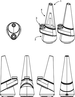
| CPC A24F 40/90 (2020.01) [A24F 40/465 (2020.01); A24F 40/51 (2020.01); H02J 50/10 (2016.02)] | 24 Claims |

|
1. A cap configured to releasably cover an inlet of a vaporization assembly for a portable electronic vaporizing device, wherein the vaporization assembly of the portable electronic vaporizing device comprises a housing configured to accommodate a container therein, the container being capable of holding a vaporizable product, an inlet configured to receive a flow of gas into the housing, a heating device capable of heating the vaporizable product held in the container, and one or more outlets capable of exhausting the flow of gas having vaporizable product therein from the vaporization assembly,
wherein the cap comprises:
a first inner cap portion comprising an outer sidewall;
a second outer cap portion comprising an inner sidewall that at least partly circumferentially surrounds the outer sidewall of the inner cap portion;
a channel formed in between the first inner cap portion and the second outer cap portion, the channel having first and second opposing ends;
a cap inlet configured to flow gas into the first end of the channel; and
a cap outlet configured to exhaust gas from the second end of the channel;
wherein the cap is configured to flow gas therethrough from the cap inlet to the cap outlet via the channel, to introduce gas into the vaporization assembly, when the cap is positioned to cover the inlet of the vaporization assembly.
|