| CPC H02J 9/068 (2020.01) [H01M 10/44 (2013.01); H02J 7/0048 (2020.01); H02J 7/00304 (2020.01); H02J 7/007182 (2020.01); H01M 10/0525 (2013.01)] | 14 Claims |

|
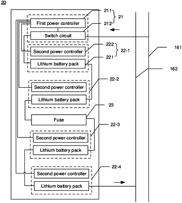
1. An apparatus for controlling a battery module, comprising:
a switch circuit, coupled with the battery module in series between a first busbar and a second busbar, to form a conductive loop comprising the switch circuit, the battery module, the first busbar, and the second busbar; and
a first power controller, coupled with the switch circuit, the battery module, the first busbar, and the second busbar, and configured to:
detect a voltage between the first busbar and the second busbar, and monitor a voltage and a power of the battery module;
enter a charging mode in a case of the voltage between the first busbar and the second busbar being greater than the voltage of the battery module and the power of the battery module being smaller than a first preset power, and under the charging mode, control the switch circuit to conduct in a first direction, to charge the battery module via the conductive loop by using the voltage between the first busbar and the second busbar; and
enter a discharging mode in a case of the voltage between the first busbar and the second busbar being smaller than the voltage of the battery module and the power of the battery module being greater than a second preset power, and under the discharging mode, control the switch circuit to conduct in a second direction opposite to the first direction, to cause the battery module to supply power to the first busbar and the second busbar via the conductive loop, wherein
the switch circuit comprises a first branch and a second branch, the first branch comprises a first contactor and a first diode, wherein a control end of the first contactor is coupled with the first power controller, a first end of the first contactor is coupled with the battery module, a second end of the first contactor is coupled with a negative electrode of the first diode, and a positive electrode of the first diode is coupled with the first busbar; and the second branch comprises a second contactor and a second diode, wherein a control end of the second contactor is coupled with the first power controller, a first end of the second contactor is coupled with the second end of the first contactor, a second end of the second contactor is coupled with the first busbar, a positive electrode of the second diode is coupled with the first end of the first contactor, and a negative electrode of the second diode is coupled with the first end of the second contactor;
the first power controller is configured to: under the charging mode, turn on the first contactor and turn off the second contactor, so as to conduct the first branch in the first direction; and under the discharging mode, turn on the second contactor and turn off the first contactor, so as to conduct the second branch in the second direction;
the apparatus for controlling battery module further comprises a circuit breaker, wherein the circuit breaker is coupled in the conductive loop and coupled with the first power controller; and
the first power controller is further configured to: after turning off the first contactor, detect a voltage between the first end of the first contactor and the second end of the first contactor, and in a case of the voltage between the first end of the first contactor and the second end of the first contactor being smaller than a first preset voltage, switch the circuit breaker from a conductive state to a cutoff state; and after turning off the second contactor, detect a voltage between the first end of the second contactor and the second end of the second contactor, and in a case of the voltage between the first end of the second contactor and the second end of the second contactor being smaller than a second preset voltage, switch the circuit breaker from the conductive state to the cutoff state.
|