| CPC G05G 13/00 (2013.01) [G05G 1/01 (2013.01); G05G 1/02 (2013.01); G05G 5/05 (2013.01); H01H 13/14 (2013.01); G05G 2505/00 (2013.01)] | 8 Claims |

|
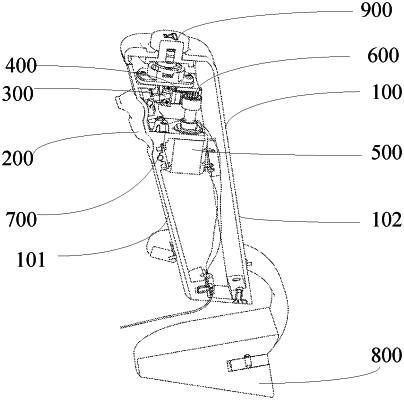
1. A speed regulating hand brake mechanism, comprising:
a housing (100), wherein an installation cavity is defined inside the housing (100);
a speed regulating button (200),wherein the speed regulating button (200) is hinged to the side wall of the housing (100);
a driving part (300) wherein the installation cavity is internally provided with the driving part (300) hinged to the speed regulating button (200);
a rack (400), wherein the rack (400) is hinged to the driving part (300) and can slide along the inner wall of the installation cavity in a horizontal direction after receiving the pressing force transmitted from the speed regulating button (200);
an encoder (500), wherein the encoder (500) is fixed on a first fixing plate (104) in the installation cavity, the rack (400) drives a gear (600) arranged at the top of the encoder (500) to rotate, and a code value output by the encoder (500) is changed;
a return piece (700), wherein an elastic end (701) of the return piece (700) is located inside the speed regulating button (200), and the other side of the return piece (700) is fixed on the inner wall of the installation cavity and is used for resetting the speed regulating button (200);
wherein the driving part (300) comprises a fixing base (301), a connecting rod (302) and a connecting base (303);
the fixing base (301) is fixed to the top of the inner side of the speed regulating button (200), and the connecting base (303) is integrally connected to one end of the rack (400):
two ends of the connecting rod (302) are provided with hinge shafts in different directions, and the two ends of the connecting rod (302) are respectively hinged to a first hinge hole on the fixing base (301) and a second hinge hole on the connecting base (303).
|