| CPC G01W 1/14 (2013.01) [G08B 21/182 (2013.01)] | 4 Claims |

|
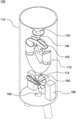
1. A self-powered apparatus for measuring precipitation, comprising:
a housing in which an inner space is formed;
a display unit including one or more display lights capable of displaying an amount of precipitation, wherein the display lights are formed on at least one of outer surfaces of the housing;
a water collecting vessel, formed within an upper part of the housing, having a funnel-shaped space to which the precipitation is introduced and gathered at a vertex part of the funnel-shaped space;
a cup module, positioned below the water collecting vessel, having an accommodating space for accommodating the precipitation dropped from the vertex part of the funnel-shaped space of the water collecting vessel, wherein, in response to a weight of the precipitation accommodated in the accommodating space exceeding a predetermined threshold, the cup module is moved along a predetermined trajectory to thereby discharge the precipitation accommodated in the accommodating space downwards;
an electric signaling unit, formed on a certain area of the inner space, for acquiring information on a movement of the cup module along the predetermined trajectory and generating an electric signal related to the amount of the precipitation, wherein the electric signal serves as a control signal for controlling at least one of the display lights;
a guiding module, positioned below the cup module, for guiding the precipitation discharged from the cup module to be moved to a triggering point opening formed on a lower part thereof;
a self-powered generator, positioned below the guiding module, for converting potential energy of the precipitation to electric energy by using the precipitation falling from the triggering point opening to the self-powered generator, wherein the guiding module is positioned below the cup module and above the self-powered generator; and
a final drainage opening, formed at a lower part of the housing such that the precipitation having been used in generating the electric energy by the self-powered generator is finally drained;
wherein the self-powered generator includes: a waterwheel that transforms the potential energy of the precipitation to kinetic energy corresponding to rotational motion as the precipitation dropping downwards from the triggering point opening strikes at least one surface thereof; a generating unit for transforming the kinetic energy to the electric energy; and an internal storage battery capable of storing the electric energy generated by the generating unit, and
wherein the cup module includes: a first cup having a first accommodating space positioned in a first direction from a separation unit formed at a central part thereof and a second cup having a second accommodating space positioned in a second direction from the separation unit formed at the central part thereof, and wherein, in response to the weight of the precipitation filling the first accommodating space exceeding the predetermined threshold, the first cup tilts to the first direction by the weight of the precipitation to thereby discharge the precipitation accommodated in the first accommodating space through the guiding module, and, in response to the precipitation dropped from the water collecting vessel filling the second accommodating space while the precipitation accommodated in the first accommodating space is discharged through the guiding module, the second cup tilts to the second direction by the weight of the precipitation to thereby discharge the precipitation accommodated in the second accommodating space through the guiding module,
wherein the cup module further includes: a (1-1)-st metal extruding rod formed on a lower surface of the first cup; a (1-2)-nd metal extruding rod formed on a lower surface of the second cup; and a reed switch module formed on a lower surface of the central part of the cup module, wherein a (2-1)-st metal extruding rod is formed on a first surface of the reed switch module such that the (2-1)-st metal extruding rod is in contact with the (1-1)-st metal extruding rod according to tilting of the first cup to the first direction and wherein a (2-2)-nd metal extruding rod is formed on a second surface of the reed switch module such that the (2-2)-nd metal extruding rod is in contact with the (1-2)-nd metal extruding rod according to tilting of the second cup to the second direction, and
wherein, in response to the weight of the precipitation filling the first accommodating space exceeding the predetermined threshold, the first cup tilts to the first direction by the weight of the precipitation to thereby make first contacts between the (1-1)-st metal extruding rod and the (2-1)-st metal extruding rod, and, in response to the precipitation dropped from the water collecting vessel filling the second accommodating space while the precipitation accommodated in the first accommodating space is discharged through the guiding module, the second cup tilts to the second direction by the weight of the precipitation to thereby make second contacts between the (1-2)-nd metal extruding rod and the (2-2)-nd metal extruding rod, and wherein the electric signal is generated based on the first contacts and the second contacts in a pulse form.
|