| CPC F23R 3/10 (2013.01) [F01D 9/023 (2013.01); F01D 9/04 (2013.01); F01D 9/06 (2013.01); F02C 3/06 (2013.01); F04D 29/544 (2013.01); F05D 2220/32 (2013.01); F05D 2240/35 (2013.01); F05D 2250/13 (2013.01)] | 14 Claims |

|
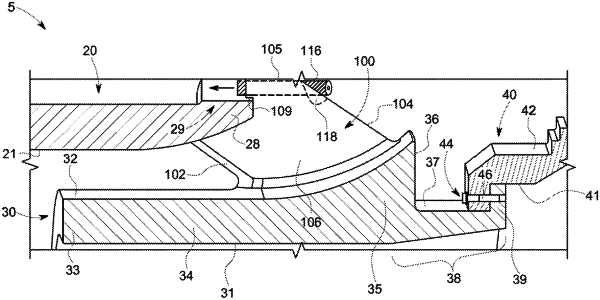
1. A diffuser assembly for a gas turbomachine comprising:
a forward casing disposed at an aft end of a compressor of the gas turbomachine;
an inner barrel member disposed radially inward of the forward casing; and
an array of radial flow splitters extending from the inner barrel member to the forward casing, each radial flow splitter of the array of radial flow splitters comprising a leading edge facing into a flow of air from the compressor, a trailing end wall opposite the leading edge, a pair of side walls extending between the leading edge and the trailing end wall, and a longitudinal axis extending through the leading edge and the trailing end wall;
wherein a width of each radial flow splitter of the array of radial flow splitters increases from the leading edge to the trailing end wall; and
wherein the pair of side walls diverge away from the longitudinal axis in a downstream direction corresponding to the flow of air, wherein each radial flow splitter of the array of radial flow splitters comprises a top surface extending from a respective leading edge to a respective trailing end wall and extending between the pair of side walls, wherein the top surface comprises a mounting element configured to engage a mounting feature on the forward casing, and wherein each radial flow splitter of the array of radial flow splitters is coupled to the forward casing through the mounting element with a mechanical fastener, the mechanical fastener disposed within a countersink region defined in the trailing end wall and the top surface.
|