| CPC F16F 9/19 (2013.01) [F16F 9/3214 (2013.01); F16F 9/3221 (2013.01); F16F 9/3228 (2013.01); F16F 9/3235 (2013.01); F16F 9/3405 (2013.01); F16F 9/368 (2013.01); F16F 9/585 (2013.01); B60G 13/08 (2013.01); B60G 17/08 (2013.01); B60G 2202/24 (2013.01); B60G 2204/62 (2013.01); B60G 2206/41 (2013.01); B60G 2500/10 (2013.01); B60G 2800/162 (2013.01); F16F 9/185 (2013.01); F16F 2222/12 (2013.01); F16F 2228/066 (2013.01); F16F 2230/0005 (2013.01); F16F 2230/42 (2013.01); F16F 2232/08 (2013.01); F16F 2234/04 (2013.01)] | 30 Claims |

|
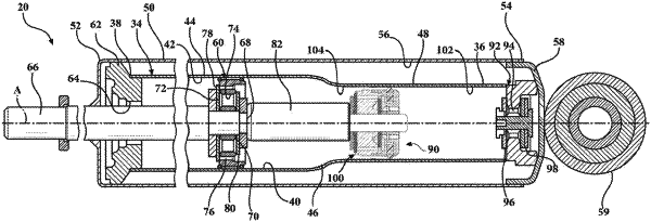
1. A hydraulic damper assembly comprising:
a housing disposed on a center axis extending between a first end and a second end defining a fluid chamber extending along said center axis for containing a working fluid;
a main piston slidably disposed in said fluid chamber dividing said fluid chamber into a first chamber and a second chamber, said first chamber extending between said first end and said main piston and said second chamber extending between said second end and said main piston;
a piston rod extending along said center axis and attached to said main piston for moving said main piston between a compression stroke and a rebound stroke;
an additional piston, located in said fluid chamber, coupled to said piston rod and axially spaced from said main piston to provide an additional damping force during said compression stroke and said rebound stroke;
said additional piston including a main body defining a compression channel and a rebound channel for allowing the working fluid to flow through said additional piston during said compression stroke and said rebound stroke, respectively;
a securing member attached to said piston rod for securing said additional piston to said piston rod, said securing member defining an outer groove extending radially inwardly toward said center axis; and
a piston ring located in said outer groove between said additional piston and said securing member, wherein said piston ring is radially spaced from said securing member to allow said piston ring to move radially between an expanded position and a compression position, with said expanded position being defined as said piston ring being spaced from said housing and said compressed position being defined as said piston ring being in engagement with said housing to align said additional piston with said housing,
wherein the hydraulic damper assembly further includes a rebound retainer disposed between said main body and said securing member, said outer groove being bounded by said rebound retainer and said securing member.
|