| CPC F03B 13/10 (2013.01) [F03B 13/264 (2013.01); H02K 7/1876 (2013.01)] | 2 Claims |

|
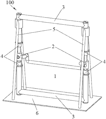
1. A vortex-induced vibration power generation device configured to generate electricity by converting ocean current energy into mechanical energy and converting the mechanical energy into electrical energy, the device comprising:
(A) a fixation arrangement including a base and a rack fixedly connected to the base;
(B) a frame including an upper portion and a lower portion, each of the upper and lower portions comprising a pair of sleeves and a connection rod extending between the pairs of sleeves, each of the sleeves having:
a cavity extending from an open end to a sealed end;
a rotatable magnet adjacent to the sealed end;
a power generating coil mounted in a coil groove extending circumferentially along at least a portion of an inner wall of the cavity; and
a sleeve flange extending radially outward from the open end;
(C) a pair of vibration guide rods, each of the vibration guide rods including:
a shaft extending from a first end to a second end;
a pair of anti-release rings configured to restrict longitudinal movement of the vibration guide rods relative to the frame;
a first and a second ring-shaped magnet mounting groove, the first ring-shaped magnet mounting groove extending circumferentially along at least a portion of an upper portion of the shaft and the second ring-shaped magnet mounting groove extending circumferentially along at least a portion of a lower portion of the shaft;
a first ring-shaped magnet mounted in the first ring-shaped magnet mounting groove and a second ring-shaped magnet mounted in the second ring-shaped magnet mounting groove;
a first fixed magnet fixedly attached to the first end of the shaft and a second fixed magnet fixedly attached to the second end of the shaft; and
a first shift fork structure fixedly attached to the first fixed magnet and a second shift fork structure fixedly attached to the second fixed magnet, wherein each of the first and second shift fork structures is configured for driving rotation of one of the rotatable magnets; and
(D) an oscillation rod extending from a first end to a second end, the first end of the oscillation rod coupled to a first one of the vibration guide rods and the second end of the oscillation rod coupled to a second one of the vibration guide rods,
wherein the upper portion of the frame is fixedly coupled to the rack and the lower portion of the frame is fixedly coupled to the base.
|