| CPC F01D 9/065 (2013.01) [F01D 5/147 (2013.01); F01D 5/282 (2013.01); F01D 5/284 (2013.01); F05D 2240/12 (2013.01); F05D 2300/6033 (2013.01)] | 18 Claims |

|
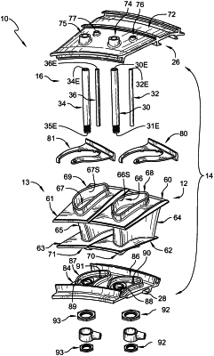
1. A turbine vane assembly for use in a gas turbine engine, the turbine vane assembly comprises
a ceramic matrix composite vane adapted to interact with hot gases flowing through a gas path of the gas turbine engine during use of the turbine vane assembly, the ceramic matrix composite vane including an outer platform, an inner platform spaced apart radially from the outer platform relative to an axis to define the gas path therebetween, and an airfoil that extends radially between the outer platform and the inner platform,
a metallic vane support assembly that extends circumferentially relative to the axis and is configured to receive loads applied to the ceramic matrix composite vane during use of the turbine vane assembly, the metallic vane support assembly including an outer vane support located radially outward of the outer platform of the ceramic matrix composite vane and an inner vane support located radially inward of the inner platform of the ceramic matrix composite vane, and
a spar system that includes a first spar that extends radially inward from the outer vane support through an interior cavity of the ceramic matrix composite vane and couples with the inner vane support so as to transfer loads applied to the inner vane support to the outer vane support and a second spar spaced apart axially from the first spar relative to the axis that extends radially inward from the outer vane support through the interior cavity of the ceramic matrix composite vane and couples with the inner vane support to transfer the loads applied to the inner vane support to the outer vane support and block twisting of the ceramic matrix composite vane during use of the turbine vane assembly,
wherein the inner vane support includes an inner mount platform that extends circumferentially at least partway about the axis and an airfoil-shaped ridge that extends radially outward form the inner mount platform, the vane further includes an inner mount that extends radially inward from the inner platform, and the airfoil-shaped ridge receives the inner mount of the vane and is engaged with the inner mount to transfer the force loads from the ceramic matrix composite vane to the first spar, and
wherein the interior cavity of the ceramic matrix composite vane extends through the outer platform, the inner platform, the inner mount, and the airfoil, the interior cavity is airfoil-shaped, and the first spar and the second spar are spaced apart from an interior surface that defines the interior cavity of the ceramic matrix composite vane.
|