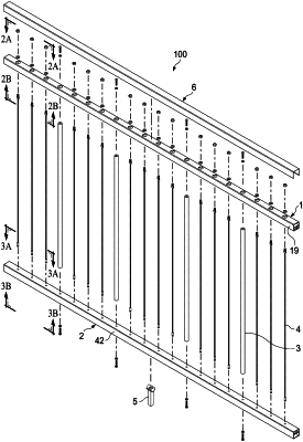
| CPC E04F 11/1817 (2013.01) [E04F 11/1859 (2013.01); E04F 2011/1823 (2013.01)] | 20 Claims |

|
1. A rail panel, comprising:
a top rail comprising a bottom wall, a top wall, and a pair of internal walls running a length of the top rail and extending toward the top wall, the top wall of the top rail defining a plurality of fastener receiving holes spaced apart along the length of the top rail, the bottom wall of the top rail defining a plurality of top cable holes spaced apart along the length of the top rail, the fastener receiving holes being larger in size than the top cable holes;
a bottom rail comprising a top wall, a bottom wall, a first side wall, a second side wall disposed opposite the first side wall, and an internal wall running a length of the bottom rail and extending from the first side wall to the second side wall, the top wall of the bottom rail defining a plurality of bottom cable holes disposed spaced apart along the length of the top wall of the bottom rail, the bottom wall of the bottom rail defining a plurality of clip receiving holes spaced apart along the length of the bottom wall of the bottom rail, the clip receiving holes being larger in size than the bottom cable holes;
a plurality of vertical cables extending from the top rail to the bottom rail, a top end of each the plurality of vertical cables extending through a respective top cable hole, and a bottom end of each of the plurality of vertical cables extending through a respective bottom cable hole;
a plurality of threaded swage fittings, each coupled to a respective top end of one of the plurality of vertical cables, each threaded swage fitting received between the pair of internal walls of the top rail such that the pair of internal walls inhibit rotation of the threaded swage fitting, each of plurality of threaded swage fittings and each of the top cable holes being sized to prevent the threaded swage fitting from passing through the top cable hole;
a plurality of clip receiving swage fittings, each coupled to a respective bottom end of one of the plurality of vertical cables and sized to pass through the bottom cable holes;
a plurality of clips, each received by a respective clip receiving swage fitting, each clip and each bottom cable hole sized to prevent the clip from passing through the bottom cable hole; and
a rigid support member extending from the top rail to the bottom rail.
|