| CPC B61C 17/00 (2013.01) [B61C 3/00 (2013.01); B61C 17/04 (2013.01); B61D 15/00 (2013.01); B61D 17/10 (2013.01); B61D 37/00 (2013.01)] | 9 Claims |

|
1. A railway power car comprising a body extending in a longitudinal direction; the body comprising a floor and two side walls defining a technical room,
the power car further comprising cabinets accommodated in the technical room, said cabinets capable of housing electrical and/or electronic and/or pneumatic equipment;
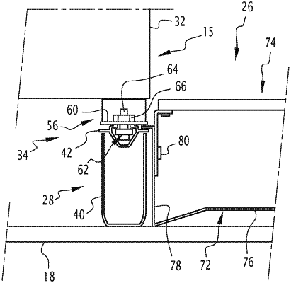
the power car further comprising at least two rails disposed on the floor, each of said rails extending in the longitudinal direction with a substantially constant cross-section, an upper part of each of said rails forming a first means of joining with one or more cabinets;
wherein each cabinet comprises at least one foot, said at least one foot comprising a second means of joining capable of mating with the first means of joining of one of said rails,
wherein each first means of joining and each second means of joining are configured so that each cabinet can be fastened to said corresponding rail at an infinite number of positions along said rail;
wherein two of the rails are disposed on either side of a central corridor extending in the longitudinal direction in the technical room, the one or more cabinets being disposed along the side walls on both sides of said central corridor;
wherein the power car further comprises a gutter disposed on the floor in the central corridor, said gutter extending in the longitudinal direction, said gutter capable of accommodating equipment cables and/or channels of the power car; and
wherein the gutter comprises perforations disposed at regular intervals in the longitudinal direction.
|