| CPC B28C 5/402 (2013.01) [B28C 5/40 (2013.01); E04G 21/02 (2013.01)] | 10 Claims |

|
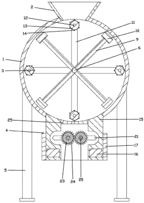
1. A fiber pre-dispersing device for fiber reinforced concrete, comprising: a dispersing chamber (1), wherein a feed inlet is installed on an upper side of the dispersing chamber (1), a hopper (2) is installed in the feed inlet, a first dispersing device (3) is installed in the dispersing chamber (1), a discharge outlet is installed at a bottom of the dispersing chamber (1) and connected with a second dispersing device (4), grooves are arranged on two sides of the dispersing chamber (1), and supporting legs (5) are installed in the grooves;
wherein the first dispersing device (3) comprises a main shaft (6), both two sides of the main shaft (6) are connected with bearings (7), and the bearings (7) are installed in the dispersing chamber (1), an end of the main shaft (6) is connected with a first motor (8), the first motor (8) is installed at a side of the dispersing chamber (1), the main shaft (6) is connected with four dispersing rods (9), and the four dispersing rods (9) are uniformly arranged on the main shaft (6) with an included angle of 45 degrees, an end of each of the four dispersing rods (9) is connected with a dispersing block (10), the two sides of the main shaft (6) are connected with a plurality of connecting frames (11), the plurality of connecting frames (11) are arranged at the two sides of the main shaft (6) in a cross shape, connecting rods (12) are connected between corresponding two of the plurality of connecting frames (11), the connecting rod (12) is sleeved with a roller (13), and a surface of the roller (13) is connected with a plurality of dispersing gears (14); and
wherein the second dispersing device (4) comprises a discharging box (15), oil cylinders (16) are installed on two sides of the discharging box (15) respectively, power output ends of the oil cylinders (16) are connected with T-shaped push plates (17) respectively, two sides of each of the T-shaped push plates (17) are connected with slide plates (18), the discharging box (15) is provided with chutes (18), the slide plates (18) are slidably installed in the chutes, bearing blocks (19) are installed in the slide plates (18) respectively, rotating rods (20) are connected with the bearing blocks (19), two sides of the discharging box (15) are provided with adjusting grooves (21), the rotating rods (20) are slidably installed in the adjusting grooves (21), second motors (22) are installed on two sides of two of the slide plates (18) respectively, power output ends of the second motors (22) are connected with the rotating rods (20) respectively, each of the rotating rods (20) is connected with a grinding cylinder (23), a surface of the grinding cylinder (23) is connected with grinding gears (24), and the grinding gears (24) are arranged crosswise.
|