| CPC A61M 15/001 (2014.02) [A24B 15/167 (2016.11); A24F 40/05 (2020.01); A24F 40/10 (2020.01); A24F 40/44 (2020.01); A24F 40/48 (2020.01); A24F 40/50 (2020.01); A24F 40/51 (2020.01); A24F 40/53 (2020.01); A24F 40/65 (2020.01); A61M 11/005 (2013.01); A61M 15/002 (2014.02); A61M 15/0021 (2014.02); A61M 15/0081 (2014.02); A61M 15/0085 (2013.01); B05B 12/08 (2013.01); B05B 17/0646 (2013.01); B05B 17/0661 (2013.01); B05B 17/0669 (2013.01); B05B 17/0684 (2013.01); A61M 15/06 (2013.01); A61M 2205/0294 (2013.01); A61M 2205/276 (2013.01); A61M 2205/3368 (2013.01); A61M 2205/3375 (2013.01); A61M 2205/60 (2013.01); A61M 2205/8206 (2013.01); A61M 2205/8212 (2013.01); A61M 2205/8237 (2013.01); B06B 2201/77 (2013.01)] | 15 Claims |

|
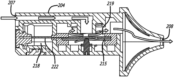
1. A mist generator device for use with a driver device, the mist generator device comprising:
a mist generator housing which is elongate and terminates at a bottom end and a top end opposite the bottom end, the housing having opposite sides positioned between the top end and bottom end, a central longitudinal axis passing through the top and the bottom end, an air inlet port formed in the bottom end, and a mist outlet port formed in the top end;
a liquid chamber provided within the mist generator housing, the liquid chamber configured to contain a liquid to be atomized;
a sonication chamber provided within the mist generator housing;
a capillary element extending between the liquid chamber and the sonication chamber such that a first portion of the capillary element is within the liquid chamber and a second portion of the capillary element is within the sonication chamber;
an ultrasonic transducer having an atomization surface which is provided within the sonication chamber, the atomization surface being in a plane that is substantially parallel to the central longitudinal axis of the housing, the ultrasonic transducer being mounted within the mist generator housing, wherein part of the second portion of the capillary element is positioned over at least part of the atomization surface, and wherein the ultrasonic transducer is configured to vibrate the atomization surface to atomize a liquid carried by the second portion of the capillary element to generate the mist comprising the atomized liquid and air within the sonication chamber;
an airflow channel within the mist generator housing which provides an air flow path between the air inlet port, the sonication chamber and the air outlet port such that a user drawing on the mist outlet port draws air through the inlet port, through the sonication chamber and out through the mist outlet port, the airflow channel is configured to change the direction of a flow of air along the air flow path as the flow of air passes into the sonication chamber, wherein the airflow channel comprises:
a first portion initiating at the air inlet port, the first portion of the air flow channel being substantially vertical and having a longitudinal axis that is substantially parallel to the central longitudinal axis of the housing and passing through the air inlet port, the first portion continuing to a second portion of the airflow channel and the second portion being in direct communication with the sonication chamber,
the second portion of the airflow channel being substantially horizontal and having a central longitudinal axis that is substantially perpendicular to the central longitudinal axis of the housing and being substantially perpendicular to the plane of the atomization surface of the ultrasonic transducer, the central longitudinal axis of the second portion intersecting at least a portion of the atomization surface such that the direction of the flow of air is substantially perpendicular to the plane of the atomization surface of the ultrasonic transducer, the substantially vertical first portion of the air flow channel extending from the bottom end to the substantially horizontal second portion of the air flow channel, wherein the mist generator device is in an upright position, the mist outlet port is at the top end and the air inlet port is at the bottom end, and the ultrasonic transducer is positioned above the air inlet port, and
a third portion of the airflow channel having a longitudinal axis that is substantially parallel to the central longitudinal axis of the housing and continuing from the sonication chamber toward the air outlet opening with the mist generated in the sonication chamber being carried by the air out through the mist outlet port for inhalation by the user; and
an identification circuitry which is provided with the mist generator housing to identify the mist generator device, the identification circuitry comprising:
a one-time programmable integrated circuit (OTP IC) having a memory which stores a unique identifier for the mist generator device, the OTP IC comprising a digital core which includes a cryptographic authenticator, and
an electrical connection which provides an electronic interface for communication with the OTP IC and the driver device.
|