| CPC A61M 5/2033 (2013.01) [A61M 5/3202 (2013.01); A61M 5/3232 (2013.01); A61M 5/3204 (2013.01); A61M 5/326 (2013.01); A61M 2005/206 (2013.01); A61M 2005/2073 (2013.01)] | 30 Claims |

|
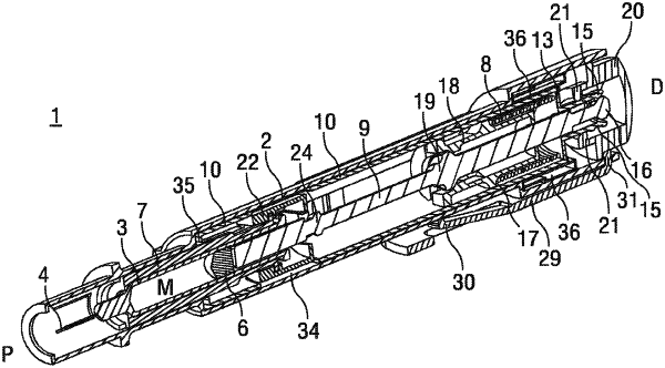
1. An auto-injector comprising:
a housing;
a syringe carrier retaining a syringe within the housing, the syringe containing a medicament and comprising a stopper, a hollow needle, and a distal flange, the syringe carrier comprising an inward protrusion located at a proximal end of the syringe carrier that is configured to engage a proximal portion of the syringe to limit proximal movement of the syringe relative to the syringe carrier;
a plunger rod configured to displace the stopper in a proximal direction relative to the syringe to dispense the medicament from the syringe through the hollow needle, the plunger rod having a first surface portion and a second surface portion, the first surface portion being axially spaced apart from the second surface portion;
a drive spring configured to apply a proximally-directed biasing force to the plunger rod;
a first member comprising a resilient arm comprising an inwardly-directed protrusion configured to releasably engage the first surface portion of the plunger rod to limit proximal movement of the plunger rod relative to the housing under the proximally-directed biasing force of the drive spring;
a second member comprising a distal portion surrounding the plunger rod and a proximal portion comprising a proximally-extending resilient arm comprising an inwardly-directed protrusion configured to releasably engage the second surface portion of the plunger rod to couple the second member to the plunger rod while the plunger rod moves in the proximal direction relative to the housing such that the second member proximally moves with the plunger rod and relative to the syringe and the syringe carrier; and
a third member comprising (i) a first surface region configured to engage an outer surface of the resilient arm of the first member to hold the inwardly-directed protrusion of the resilient arm of the first member in engagement with the first surface portion of the plunger rod and (ii) a recess configured to receive a portion of the resilient arm of the first member to release the held engagement of the inwardly-directed protrusion of the resilient arm of the first member with the first surface portion of the plunger rod, the third member configured to axially move relative to the housing, the syringe carrier, the first member, and the second member to change the auto-injector from a first state in which the inwardly-directed protrusion of the resilient arm of the first member is held in engagement with the first surface portion of the plunger rod and proximal movement of the plunger rod relative to the housing is limited to a second state in which the portion of the resilient arm of the first member has outwardly deflected into the recess of the third member and the held engagement between the inwardly-directed protrusion of the resilient arm of the first member and the first surface portion of the plunger rod has been released such that proximal movement of the plunger rod relative to the housing is allowed.
|