| CPC H04R 9/025 (2013.01) [H02K 33/16 (2013.01); H04R 11/02 (2013.01)] | 24 Claims |

|
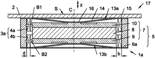
1. An electrodynamic actuator (1a, 1b), which is designed to be connected to a backside of a plate like structure (2) opposite to a sound emanating surface (S) of the plate like structure (2), and which comprises:
a coil arrangement (3a, 3b) with at least one voice coil (4a, 4b), which has an electrical conductor in the shape of loops running around a coil axis (C) in a loop section;
a magnet system (5), comprising a static magnetic circuit part (6a . . . 6F), which is arranged in fixed relation to the coil arrangement (3a, 3b), and a movable magnetic circuit part (7, 7a . . . 7f), wherein the magnet system (5) is designed to generate a magnetic field (B1, B2) transverse to the conductor in the loop section; and
a spring arrangement (12) coupling the static magnetic circuit part (6a . . . 6F) to the movable magnetic circuit part (7, 7a . . . 7f) and allowing a relative movement between the static magnetic circuit part (6a . . . 6F) and said movable magnetic circuit part (7, 7a . . . 7f) in an excursion direction (z) parallel to the coil axis (C),
wherein both the spring arrangement (12) and the magnet system (5) provide a total restoring force (FT) directed towards an idle position (P0) of the movable magnetic circuit part (7, 7a . . . 7f), which idle position (P0) is defined as the position of the movable magnetic circuit part (7, 7a . . . 7f) when no current (I) flows through the at least one voice coil (4a, 4b),
wherein a ratio between a differential total restoring force (ΔFT) and a differential excursion (Δz) of the movable magnetic circuit part (7, 7a . . . 7f) is defined as a total restoring force gradient (ΔFT/Δz), and
wherein a part of the total restoring force gradient (ΔFT/Δz) caused by the magnet system (5) is at least 10% of the total restoring force gradient (ΔFT/Δz) in said idle position (P0) of the movable magnetic circuit part (7, 7a . . . 7f).
|