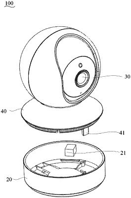
| CPC H04N 23/695 (2023.01) [H04N 23/64 (2023.01)] | 18 Claims |

|
1. A control circuit of a pan-tilt-zoom (PTZ) camera, comprising:
a motor drive circuit, a monitoring circuit, a gimbal motor, and a microprocessor, the motor drive circuit, the gimbal motor, and the microprocessor being electrically connected to the monitoring circuit respectively, wherein
the gimbal motor is configured to drive a rotor of the camera to rotate;
the monitoring circuit is configured to acquire a first signal between the motor drive circuit and the gimbal motor, and output a second signal to the microprocessor according to the first signal;
the microprocessor is configured to obtain an in-place status of the gimbal motor according to the second signal; and
the motor drive circuit is configured to control an operating state of the gimbal motor according to the in-place status,
wherein the first signal comprises an operating voltage, the second signal comprises an operating level, the monitoring circuit comprises a sampling resistor and an amplification and comparison circuit,
the sampling resistor is connected in series between the motor drive circuit and the gimbal motor,
the amplification and comparison circuit and the sampling resistor are connected in parallel to each other and are electrically connected to the microprocessor,
the amplification and comparison circuit is configured to output the operating level according to the operating voltage and a resistance value of the sampling resistor, and
the microprocessor is configured to obtain the in-place status of the gimbal motor according to the operating level.
|